
Method and system for purifying flue gas generated by incinerating waste materials

A purification system and waste technology, applied in the field of flue gas purification, can solve the problems of increasing metal emission concentration, long impact time, easy condensation, etc., and achieve the effect of ensuring full decomposition, eliminating dioxins, and avoiding pollution

Inactive Publication Date: 2010-10-27
于金玲
View PDF5 Cites 20 Cited by
  • Summary
  • Abstract
  • Description
  • Claims
  • Application Information

AI Technical Summary

Problems solved by technology

The release and migration of this toxic and harmful substance is a slow long-term process, the concentration of contact with the human body is generally relatively low, and the impact time is long
[0004] At the same time, because many of the wastes are incinerated in the process of metal substances, some of these heavy metals will be volatilized by incineration after high temperature incineration, and the rest will remain in the ash. The ratio of volatilization and residue is related to the boiling point of various metals. The higher the boiling point, the easier it is to condense, and the proportion of residues in the ash will increase accordingly, increasing the emission concentration of ash and metals in the flue gas during the incineration process
Moreover, a lot of waste miscellaneous copper, which itself has the conditions of the catalyst, such incineration, a large amount of heavy metals accelerate the formation of dioxin
[0005] In addition, the flue gas produced by general waste incineration also pollutes the environment to varying degrees.

Method used


Image

  • Method and system for purifying flue gas generated by incinerating waste materials
  • Method and system for purifying flue gas generated by incinerating waste materials

Examples


Embodiment Construction

[0029] The present invention will be described in detail below in conjunction with the accompanying drawings and specific embodiments.

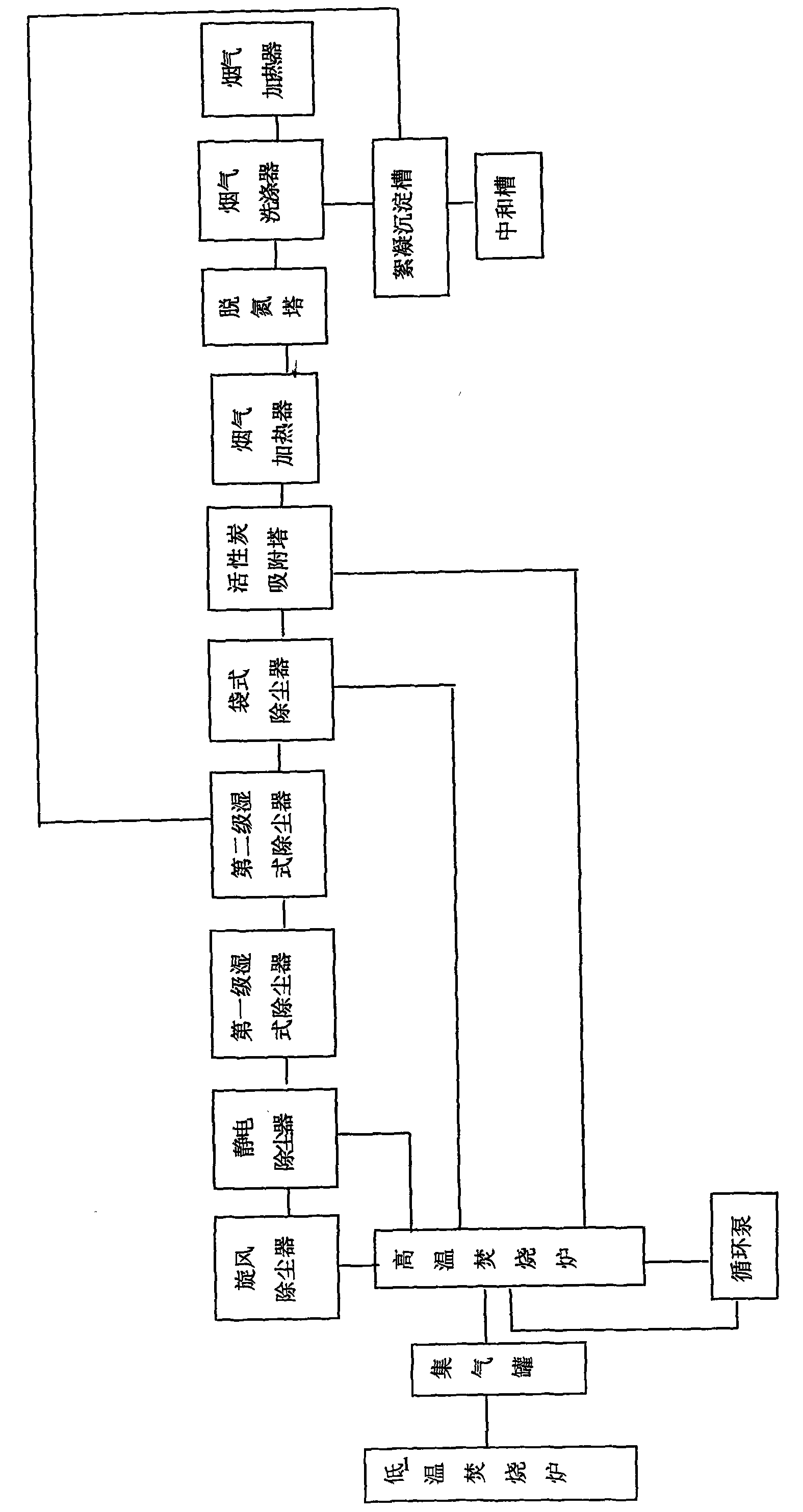
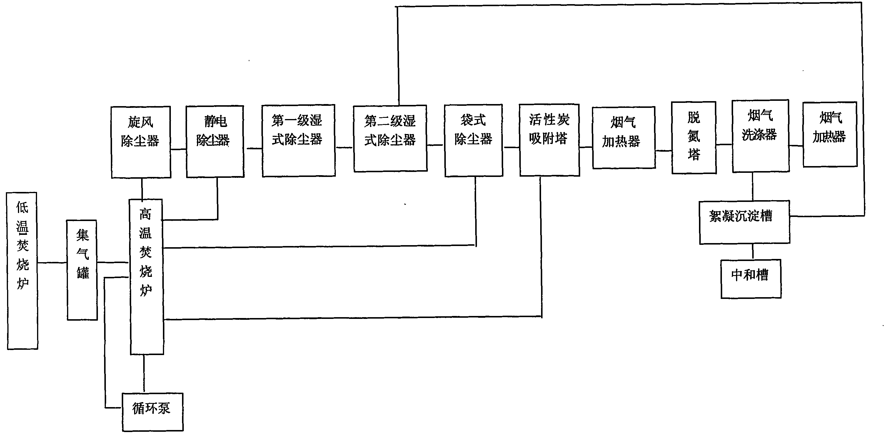
[0030] The purification method of the flue gas produced by waste incineration of the present invention comprises the following steps:

[0031] (1) High-temperature incineration: Send the waste to a high-temperature incinerator at 1000-1200°C for 1.7-3s.

[0032] (2) Dust removal and cooling treatment: After the flue gas generated by the high-temperature incinerator passes through the cyclone dust collector and the electrostatic precipitator in sequence, the temperature of the flue gas drops to 500 ° C, and then it is treated by two-stage wet dust collectors. Inject limestone solution to remove acid gas, spray NaCO solution into the second-stage wet dust collector to destroy dioxins in the flue gas, and reduce the temperature of the flue gas to below 200°C within 2-4s, so that dioxins cannot be generated. The flue gas after cooling is treated...


PUM


Abstract

The invention discloses a method and a system for purifying flue gas generated by incinerating waste materials and aims at providing a method for purifying flue gas, which can reduce the content of dioxin in the flue gas generated by incinerating waste materials, avoid the pollution of heavy metals in the waste material to the environment, and is beneficial to protecting the environment and guaranteeing the health of a human body and a purifying system for realizing the method. The method comprises the following steps of: incinerating waste materials at high temperature of 1,000-1,200 DEG C for 1.7-3s; dust-collecting and temperature-reducing treatment: treating flue gas generated by a high-temperature incineration furnace and passing through a cyclone dust collector and an electrostatic precipitator in sequence by using two-stage wet dust collectors; spraying a limestone solution into a first-stage wet dust collector to remove acid gases; spraying an NaOH solution into a second-stage wet dust collector to damage the content of the dioxin in the flue gas; carrying out active carbon power spraying treatment and active carbon adsorption treatment on the flue gas of which the temperature is reduced; and raising the temperature of the flue gas to 210 DEG C for denitrification treatment, washing and heating the denitrified flue gas, and then exhausting the heated flue gas to the atmosphere.

Description

technical field [0001] The invention relates to the field of flue gas purification, more specifically, to a method and system for purifying flue gas produced by waste incineration. Background technique [0002] Jinghai and the surrounding areas of Hebei Province bordering here are the demolition bases for the whole country. People living in this area are engaged in waste equipment and waste materials such as waste electric motors, waste transformers, and waste cables, which are purchased from developed countries such as Europe and Asia. Through demolition, the country's production resources can be supplemented, and people have gained some benefits from engaging in this industry, but it has also brought some negative impacts on the surrounding environment and caused pollution to the surrounding natural environment. [0003] In the old demolition base, the dismantled waste is incinerated on the spot, and the flue gas contains heavy metals and dioxin poisonous substances, whic...

Claims


Application Information

Patent Timeline
IPC IPC(8): B01D53/78B01D53/04B01D50/00F23J15/00
Inventor 刘闽男
Owner 于金玲
Learn More