Electrothermal cutting machine with automatic voltage-stabilized and constant-current device

A technology of automatic voltage stabilization and cutting machine, which is applied in the direction of output power conversion device, electrical components, AC power input conversion to DC power output, etc., to achieve the effect of good consistency, convenient operation and simple structure

Inactive Publication Date: 2010-10-27
吕禾
View PDF0 Cites 12 Cited by
  • Summary
  • Abstract
  • Description
  • Claims
  • Application Information

AI Technical Summary

Problems solved by technology

[0005] The technical problem to be solved by the present invention is: the electric heating wire of the electric heating cutting machine can be adjusted left and right according to the shape

Method used


Image

  • Electrothermal cutting machine with automatic voltage-stabilized and constant-current device
  • Electrothermal cutting machine with automatic voltage-stabilized and constant-current device
  • Electrothermal cutting machine with automatic voltage-stabilized and constant-current device

Examples


Embodiment 1

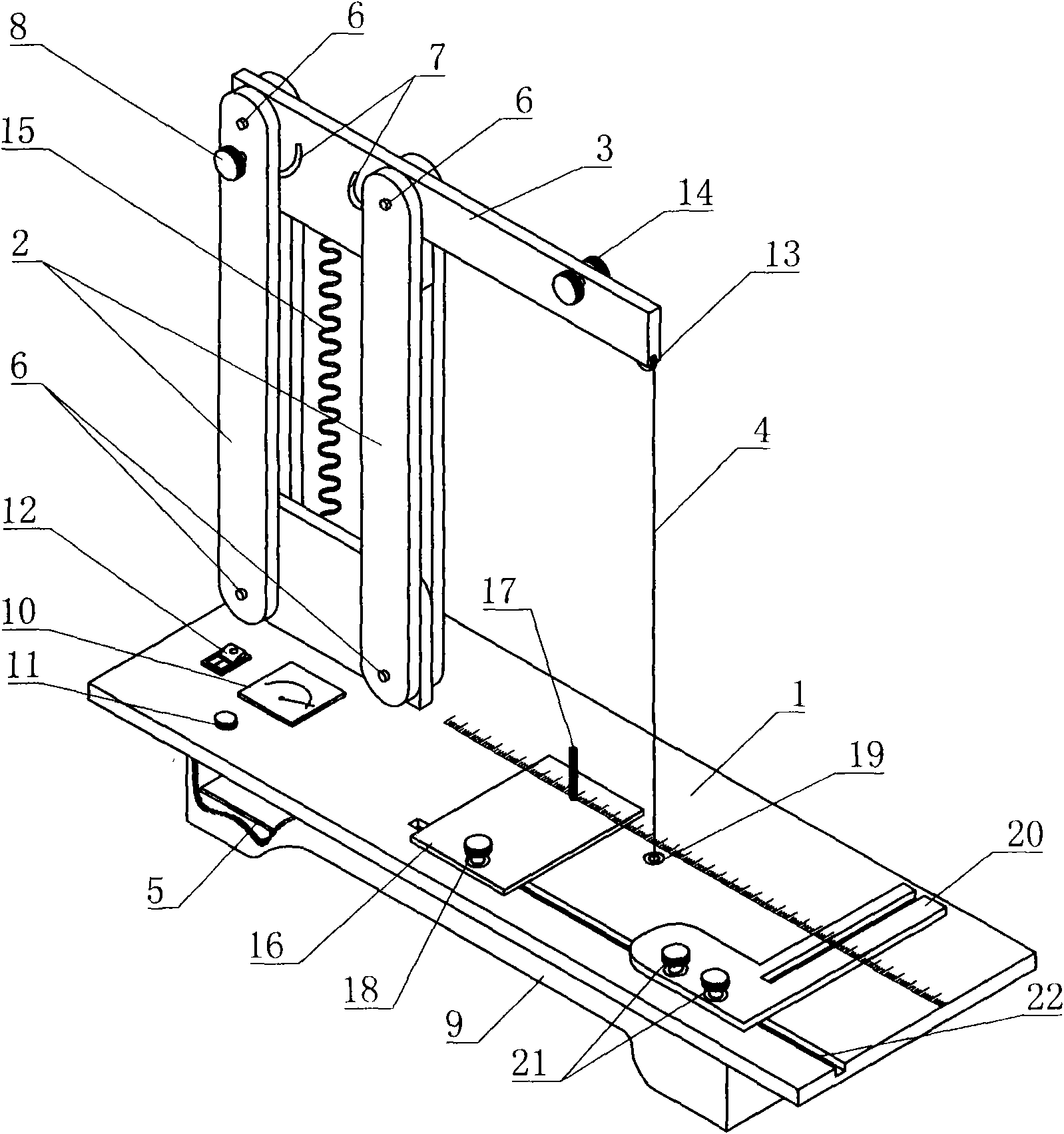
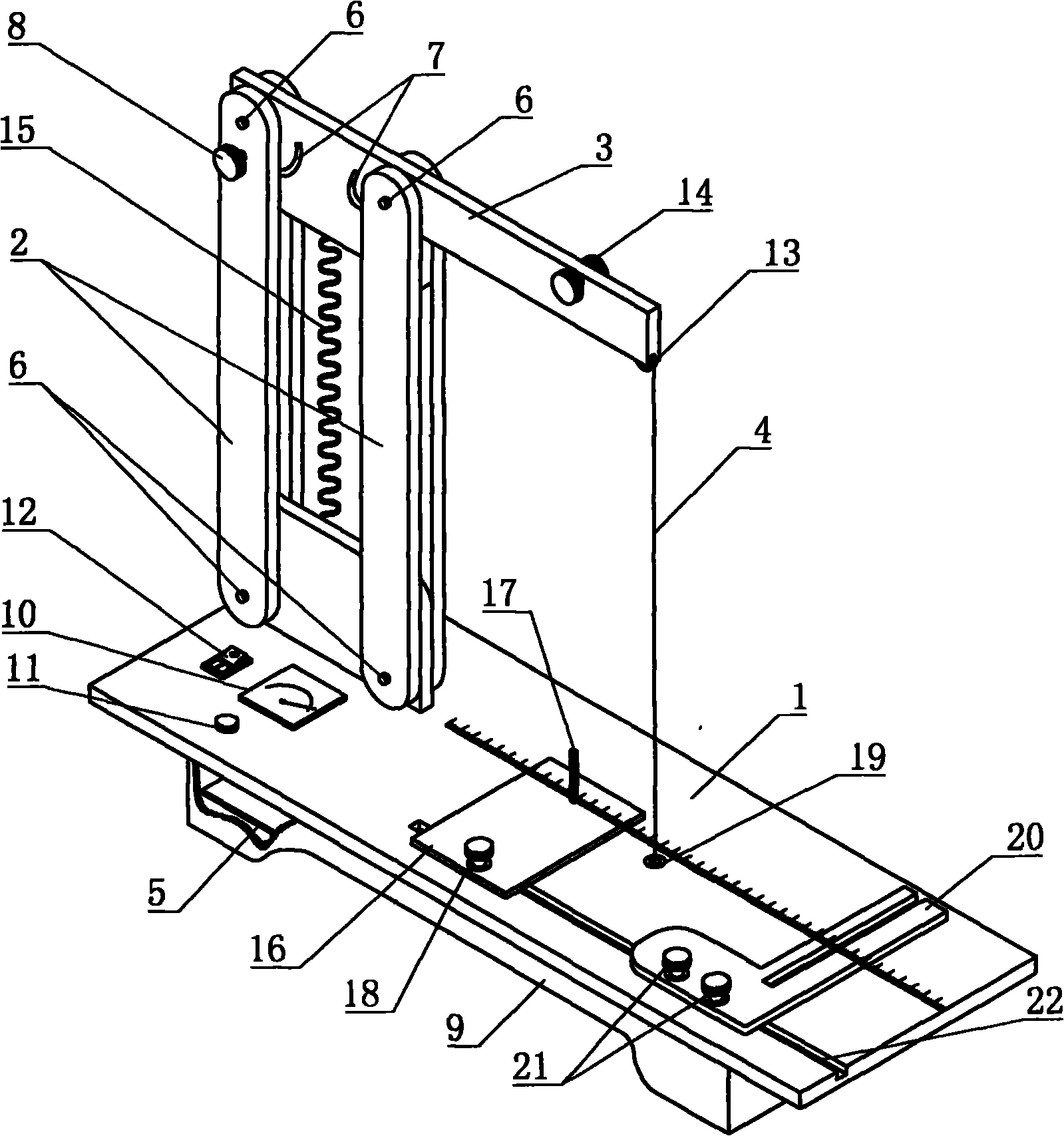
[0023] Embodiment one: figure 1 It is a structural schematic diagram of an electric thermal cutting machine equipped with an automatic voltage stabilizing constant current device in the present invention. The present invention is equipped with the electrothermal cutting machine of automatic voltage stabilizing and constant current device, is made up of work table board 1, vertical arm 2, heating wire support arm 3, heating wire 4 and the circuit board 5 of power supply heating wire working current, is characterized in that The vertical arm 2 described above is composed of two movable vertical arms parallel to each other, and a movable vertical arm shaft 6 is respectively arranged at the upper and lower ends of each movable vertical arm, and the two movable vertical arm shafts 6 at the upper end are connected with the described vertical arm shafts. The left side of the heating wire support arm 3 is movably connected, and the two movable vertical arm shafts 6 at the lower end ar...

Embodiment 2

[0025]Embodiment 2: The right end of the heating wire support arm 3 of the present invention is provided with a heating wire tension spring 13, and the heating wire 4 is tightly pressed on the heating wire tension spring 13, and then the heating wire arranged in the heating wire support arm 3 is wound on the disk 14, and be electrically connected with the helical wire 15 located in the middle of the two movable vertical arms 2, and then be connected to the positive output terminal of the power supply of the said circuit board 5. A power switch 12, a center-of-circle distance adjusting plate 16, a heating wire through hole 19, a moving square 20 and a chute 22 are arranged successively from left to right on the workbench 1. Said center-of-circle distance adjustment plate 16 is provided with a center-of-circle positioning rod 17 and a center-of-circle fixing button 18; two square-square fixing buttons 21 are also installed side by side on the described moving square 20, and the c...

Embodiment 3

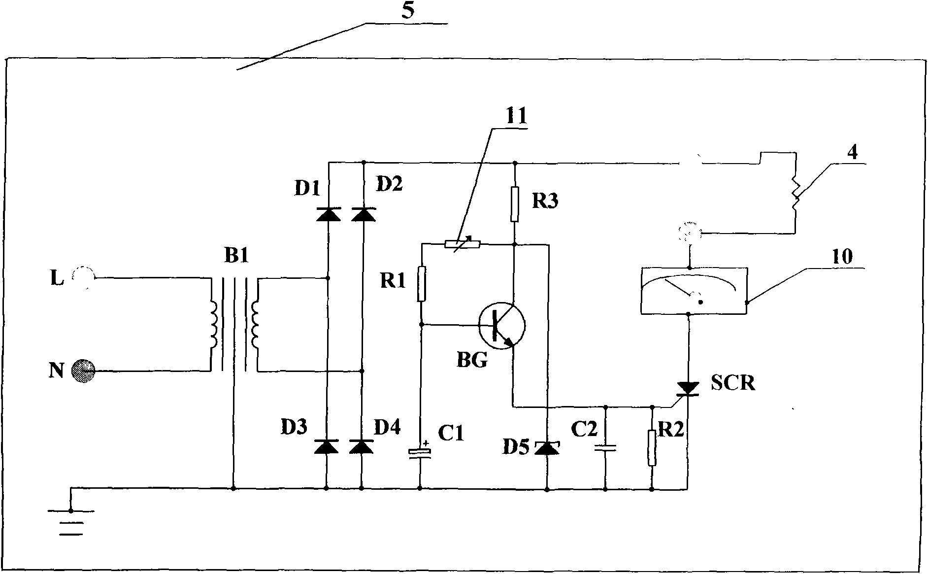
[0027] Embodiment three: the potentiometer 11 in the circuit board 5 of the present invention is also connected in series with a resistor R 1 , when the resistance value of the potentiometer is manually adjusted to the minimum value, it is affected by the series resistor R 1 The trigger current of the control pole of the thyristor SCR is also limited within the set range. The operating current of the heating wire 4 is also regulated within the set range. The base of the triode BG is connected in parallel with the negative output terminal of the power supply C 1 , with potentiometer 11 and series resistor R 1 Form a pulse phase shifting circuit. Power step-down transformer B 1 It is made of iron core inductor winding, with stable performance and low price. Parallel capacitor C between the control pole and the cathode of the thyristor SCR 2 and resistor R 2 , Improve the pulse waveform and improve the anti-jamming performance.


PUM


Abstract

The invention relates to an electrothermal cutting machine with an automatic voltage-stabilized and constant-current device, which consists of a workbench plate, a vertical arm, an electric heating wire support arm, an electric heating wire and a circuit board for supplying operating current for the electric heating wire. The electrothermal cutting machine is characterized in that the vertical arm is composed of two parallel movable vertical arms; the circuit board is provided with a silicon controlled SCR and a triode BG; and a voltage stabilizing diode is connected between the collector electrode of the BG and the output end of the negative electrode of a power source in parallel. The electrothermal cutting machine has the advantages that the electric heating wire can be obliquely adjusted from side to side; and trapezoid, cone and various combined complex shapes are cut according to the requirements of a plastic model or a packaging article; the electrothermal cutting machine has convenient operation, simple structure and good consistency; and meanwhile when power supply voltage changes upwards and downwards, the electric heating wire works at a constant power and is not burned off.

Description

technical field [0001] The invention relates to an electric heat cutting machine, especially an electric heat cutting machine equipped with an automatic voltage stabilizing constant current device. Background technique [0002] The prior art includes electric heat cutting machines for making plastic models, foam packaging products, etc., generally adopting a power transformer to manually adjust the electric heating wire current to work. As we all know, if the current flowing through the heating wire is too large, the temperature rise of the heating wire is too high, the calorific value is large, and the surface of the heating wire is burnt red and easy to break; at the same time, the slits of the cut plastic molds, foam packaging products, etc. will also be burnt. And produce waste. Conversely, if the current is too small, the temperature of the heating wire is low, the cutting speed is slow, and the efficiency is low. And the size of the current flowing through the heatin...

Claims


Application Information

Patent Timeline
IPC IPC(8): B26F3/12B26D7/26H02M7/219B26D7/08B26D7/28
Inventor 吕禾周云正
Owner 吕禾
Why Eureka
Try Eureka