Loader and circular cooling and lubricating system of torque converter thereof

A technology of circulating cooling and lubricating system, applied in lubricating system, transportation and packaging, earth mover/shovel, etc., can solve the problems of reduced working reliability, reduced reliability, difficulty in achieving cooling and lubrication, etc. Effect of cooling lubrication effect

Active Publication Date: 2010-10-27
XUZHOU XCMG DRIVELINE TECH CO LTD
View PDF4 Cites 9 Cited by
  • Summary
  • Abstract
  • Description
  • Claims
  • Application Information

AI Technical Summary

Problems solved by technology

Due to the structural characteristics of the internal circulation, the flow rate of the cooling lubricating oil is basically fixed. Therefore, under the premise that the size of the material remains unchanged, it is difficult for this system to fundamentally change the cooling performance of the three-element system.
At the same time, under high temperature working conditions, the three components will expand outward as a whole, and the internal circulation cooling and lubrication method is not ideal for cooling the three components. In this way, under the condition of high temperature and long-term operation, it will inevitably cause deformation The torque conversion coefficient of the torque converter is reduced, the temperature of the internal bearing is too high, and the working reliability is reduced.
[0007] Second, for the internal cooling and lubrication of the transfer case, since the three pumps (variable speed pump, working pump, and steering pump) are arranged in a decentralized manner, and the arrangement of the gears is fixed, a different flow rate is used outside the torque converter. The large oil spray port cools the parts in the transfer case. It is difficult to achieve the effect of all-round cooling and lubrication from the structure. The orientation of the cooling and lubricating oil is too random, and it is difficult to take care of the main components such as rolling bearings in the three pumps. , similarly, under the condition of high temperature and long-term operation, it will cause poor cooling and lubrication of the internal parts of the transfer case, aggravated wear, and reduced reliability.

Method used


Image

  • Loader and circular cooling and lubricating system of torque converter thereof
  • Loader and circular cooling and lubricating system of torque converter thereof
  • Loader and circular cooling and lubricating system of torque converter thereof

Examples


Embodiment Construction

[0043] The core of the present invention is to provide a circulating cooling and lubricating system for the torque converter to perform all-round cooling and lubricating for the internal parts of the torque converter, so that the torque converter can work for a long time under high temperature conditions.

[0044] Without loss of generality, this embodiment will be specifically described below with the loader as the main body.

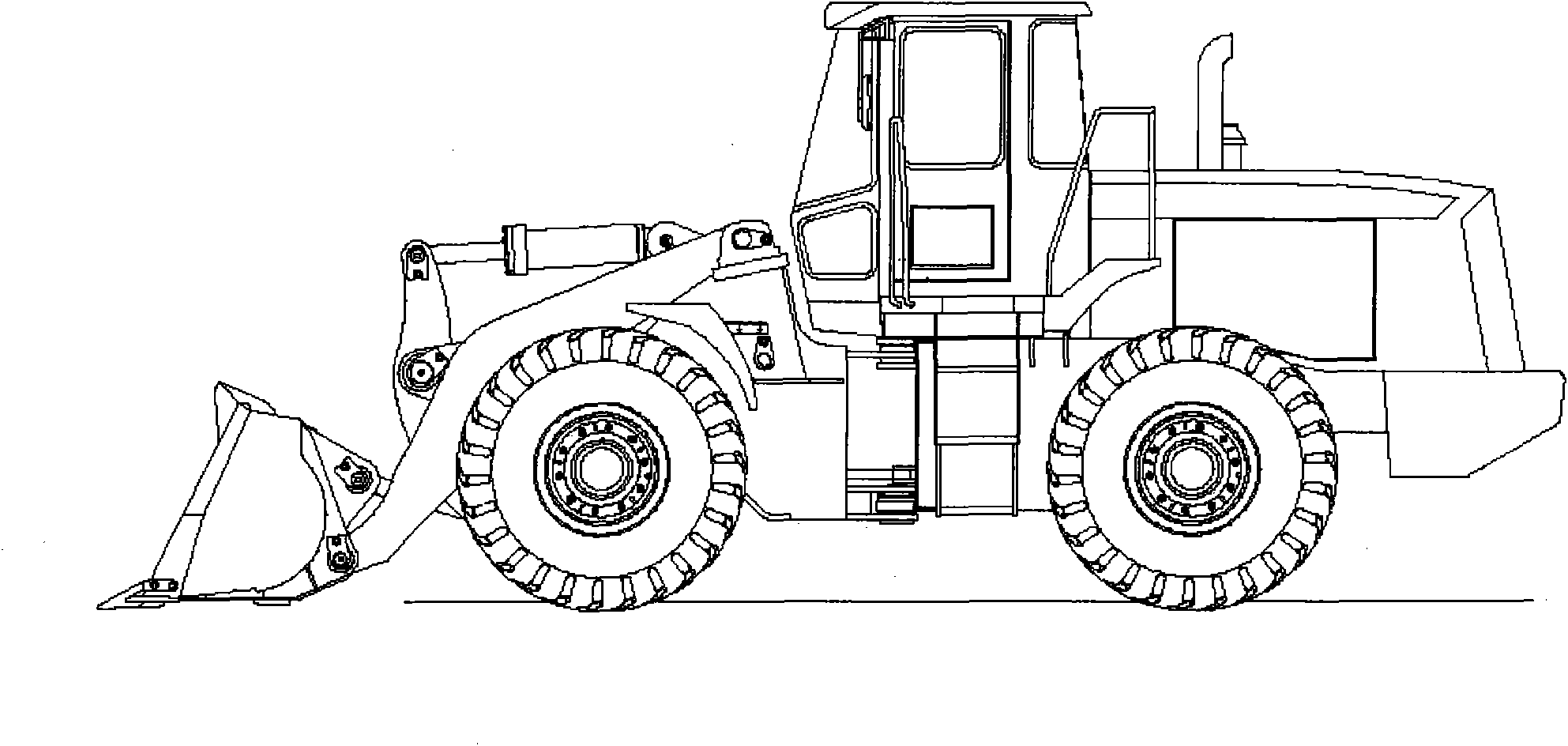
[0045] See image 3 , which is a schematic diagram of the overall structure of the loader according to this embodiment.

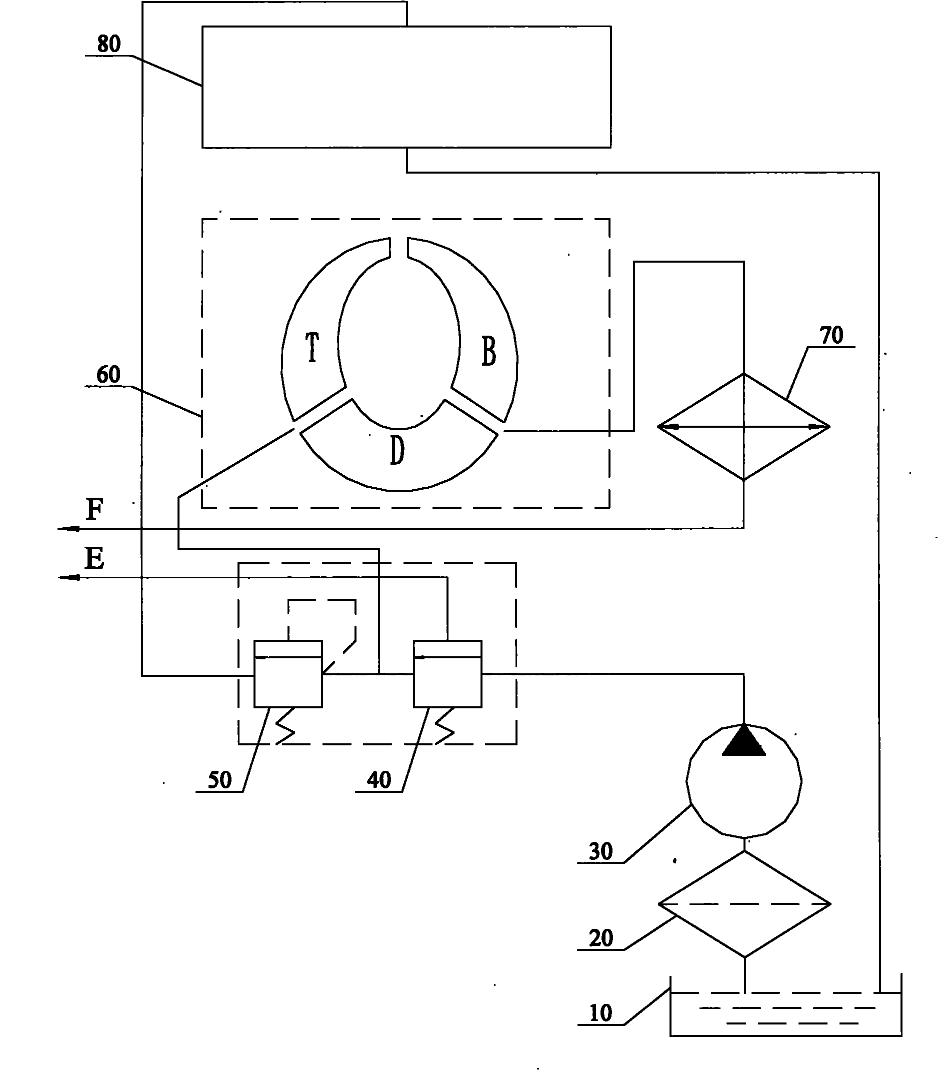
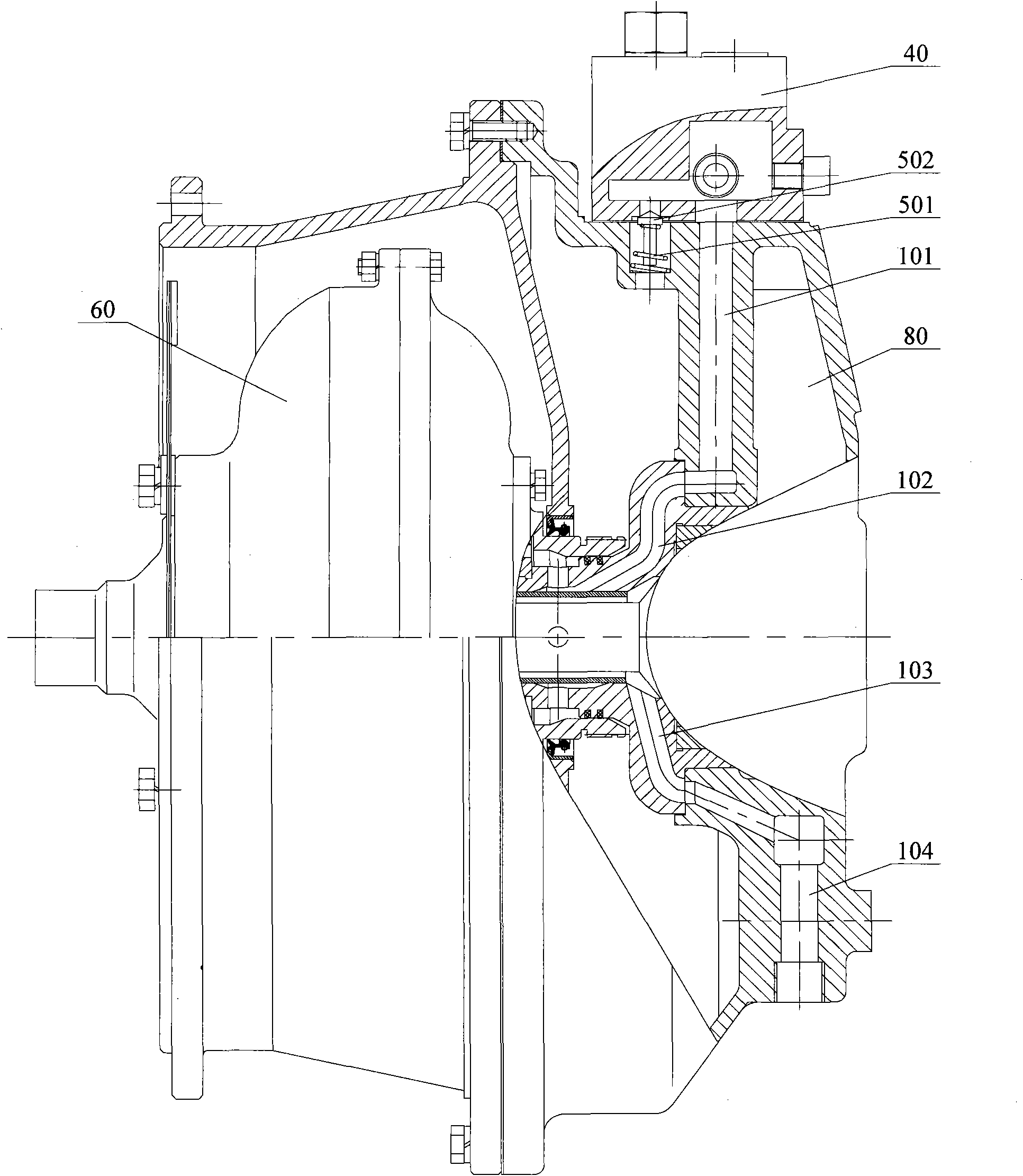
[0046] The main functional components of the loader, such as the working device, power transmission system, control system, hydraulic system and electrical system, are basically the same as those of the prior art, and those skilled in the art can fully realize them based on the prior art, so this article will not repeat them here. See Figure 4 , which is a schematic diagram of the torque converter circulating cooling and lubricat...


PUM


Abstract

The invention discloses a circular cooling and lubricating system of a torque converter. The system comprises a pump device and a gear box overflow valve; the pump device outputs pressure oil to a system pressure oil line; a liquid inlet cavity of the gear box overflow valve is communicated with the system pressure oil line, while the liquid outlet cavity of the gear box overflow valve is communicated with an inner cavity of a three-element system through a transfer case shell of the torque converter and an oil inlet on a guide wheel seat in turn; the liquid outlet of the three-element system is connected with a radiator assembly through the guide wheel seat of the torque converter and an oil outlet on the transfer case shell in turn; the system further comprises two oil injection devices of which the oil inlets are communicated with the liquid outlet cavity of the gear box overflow valve respectively, and an oil nozzle of one oil injection device is formed above a pump wheel of the three-element system, while an oil nozzle of the other oil injection device is formed above a cover wheel of the three-element system; and the liquid outlet on a housing of the three-element system is connected with the radiator assembly. Moreover, the invention further provides a loader provided with the circular cooling and lubricating system of the torque converter.

Description

technical field [0001] The invention relates to a hydraulic torque converter of engineering machinery, in particular to a cooling and lubricating system of the torque converter and a loader applying the system. Background technique [0002] The existing hydraulic torque converters for loaders generally adopt an internal circulation cooling and lubricating system. See figure 1 and figure 2 ,in, figure 1 is the schematic diagram of the system, figure 2 It is a schematic diagram of the overall structure of the torque converter. [0003] During the working process, the variable speed pump 30 runs under the drive of the engine, and pumps cooling lubricating oil from the oil tank 10 through the filter 20 . After the pressure oil enters the transmission relief valve 40, part of it flows out into the clutch system E of the transmission for its use, and the other part of the pressure oil acts on the spool of the transmission relief valve 40 to move, and all the way along the t...

Claims


Application Information

Patent Timeline
IPC IPC(8): B60R17/00E02F9/22
Inventor 邬俊奇殷琳吕培新吴凌云
Owner XUZHOU XCMG DRIVELINE TECH CO LTD
Why Eureka
Try Eureka