Cooling and lubricating system of supercharger
A cooling lubrication and supercharger technology, applied in the direction of machine/engine, engine components, mechanical equipment, etc., can solve the problems of dry grinding of supercharger rotor system, user misoperation, large resistance of cooling and lubrication passage, etc., to achieve cooling and lubrication Good effect, improve service life, solve the effect of excessive resistance
- Summary
- Abstract
- Description
- Claims
- Application Information
AI Technical Summary
Problems solved by technology
Method used
Image
Examples
Embodiment 1
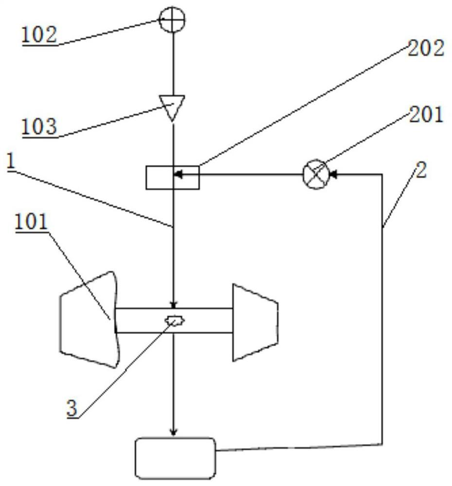
[0029] Such as figure 1 As shown, a cooling lubrication system of a supercharger includes a main circulation circuit 1 and an independent circulation branch 2; the main circulation circuit 1 includes a supercharger 101, a check valve 103 and a The main engine pump 102 of the engine, the independent circulation branch 2 includes an electronic pump 201, and the connection port 202 between the electronic pump 201 and the main circulation circuit 1 is arranged between the supercharger 101 and the main engine pump 102 The one-way valve 103 is set on the pipeline between the connection port 202 and the engine main pump 102, and the flow direction of the one-way valve 103 is set to be consistent with the main circulation circuit 1 .
[0030] The working principle of this embodiment is as follows:
[0031] When the engine receives the starting signal, the electronic pump 201 starts to run, shortening the oil supply delay time of the supercharger 101; The cooling and lubrication of ...
Embodiment 2
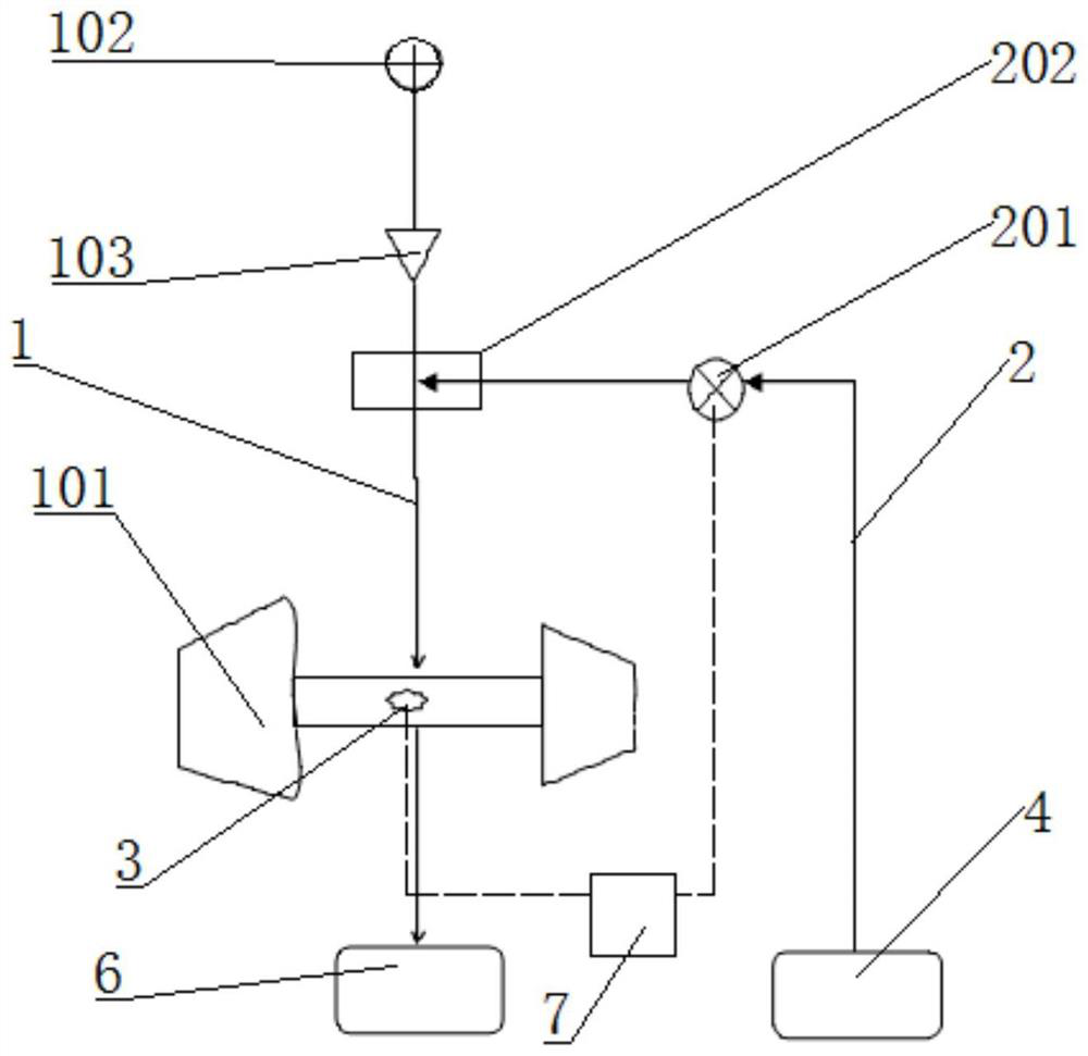
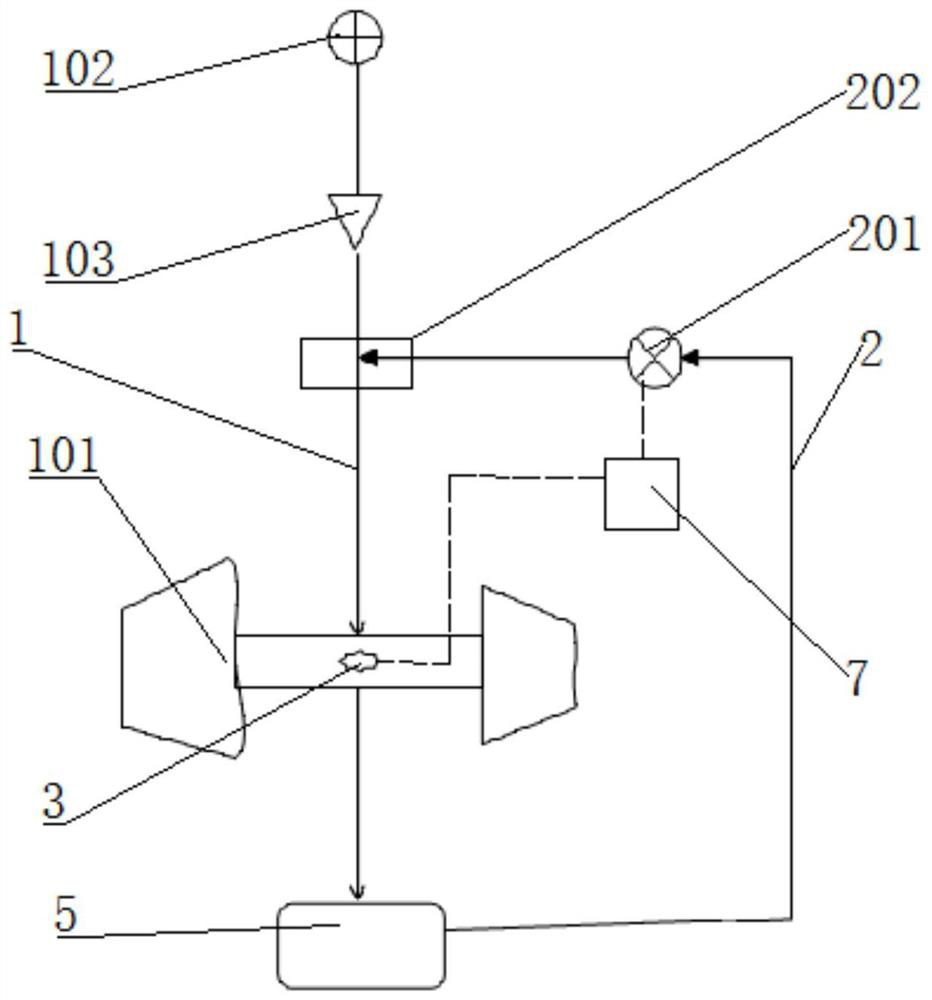
[0035] Such as figure 1 As shown, a cooling lubrication system of a supercharger includes a main circulation circuit 1 and an independent circulation branch 2; the main circulation circuit 1 includes a supercharger 101, a check valve 103 and a The main engine pump 102 of the engine, the independent circulation branch 2 includes an electronic pump 201, and the connection port 202 between the electronic pump 201 and the main circulation circuit 1 is arranged between the supercharger 101 and the main engine pump 102 The connection port 202 is a three-way structure, the check valve 103 is arranged on the pipeline between the connection port 202 and the engine main pump 102, and the flow direction of the check valve 103 It is set to be consistent with the main circulation loop 1 .
[0036] This embodiment also includes an engine control unit ECU7 and a temperature sensor 3 provided on the supercharger 101 , the temperature sensor 3 and the electronic pump 201 are both electrically...
Embodiment 3
[0039] Such as figure 2 As shown, this implementation is a further technical solution of Embodiment 2. This embodiment is specifically the cooling system of the supercharger 101, the electronic pump 201 is an electronic water pump, and the engine main pump 102 is an engine main water pump.
[0040] In the main circulation loop 1 , the coolant passes through the water inlet pipeline, the main water pump of the engine, the one-way valve 103 , the supercharger 101 , the return water pipeline, and finally enters the water circulation passage 6 .
[0041] In the independent circulation branch 2 , the coolant flows sequentially through: the auxiliary water tank in the external circulation of the engine, the electronic water pump, the connection port 202 , and then enters the main circulation circuit 1 .
[0042] The working principle of this embodiment: when the engine is running normally, the main water pump of the engine directly supplies the supercharger 101 with coolant, and th...
PUM
 Abstract
Description
Claims
Application Information
 - R&D
- Intellectual Property
- Life Sciences
- Materials
- Tech Scout
- Unparalleled Data Quality
- Higher Quality Content
- 60% Fewer Hallucinations
Browse by: Latest US Patents, China's latest patents, Technical Efficacy Thesaurus, Application Domain, Technology Topic, Popular Technical Reports.
© 2025 PatSnap. All rights reserved.Legal|Privacy policy|Modern Slavery Act Transparency Statement|Sitemap|About US| Contact US: help@patsnap.com


