Small-flow high-lift radial piston pump

A technology of radial piston pump and high head, which is applied in the field of volumetric pumps, which can solve the problems of liquid backflow and loss of volumetric efficiency, high head and small flow, etc., to achieve sealing area and length increase, small flow head, Effect of increasing discharge pressure

Inactive Publication Date: 2010-10-27
余文凌
View PDF8 Cites 6 Cited by
  • Summary
  • Abstract
  • Description
  • Claims
  • Application Information

AI Technical Summary

Problems solved by technology

[0007] The newly emerging valveless rotor pump has attracted people's attention. It has good self-priming performance, eliminates the hysteresis of the valve, has a simple structure, small volume, high reciprocating times and can transport viscous liquids, such as patent ZL021127763.8 "Rotor-type piston pump", ZL96228726.1 "double-cylinder double-acting rotor-piston pump", ZL00211851.3 "synchronous suction-discharge rotor pump", but these rotor pumps have the same common defect that they can only have a small flow rate, not a high flow rate. The reason is that the width of the sealing tongue on the pump body is equal to the diameter of the radial hole of the piston on the rotor, such as figure 1 As shown in the figure, there are pump body 1, rotor 2, piston 3, and partition tongue 4. The isolation of the high-pressure chamber and low-pressure chamber of this pump relies on the partition tongue 4 that divides the inner chamber into a suction chamber and a discharge chamber on the pump body. It acts as a valve seal, and the length of its seal width determines the performance of the seal and the level of the discharge pressure. During operation, when the diameter of the piston hole is equal to the width of the upper diaphragm 4, since the two widths are equal, Its sealing length is zero instantaneously, resulting in liquid backflow and loss of volumetric efficiency. Therefore, it is greatly restricted to increase the discharge pressure to achieve high lift, which limits its use in small flow and high lift.

Method used


Image

  • Small-flow high-lift radial piston pump
  • Small-flow high-lift radial piston pump
  • Small-flow high-lift radial piston pump

Examples


Embodiment Construction

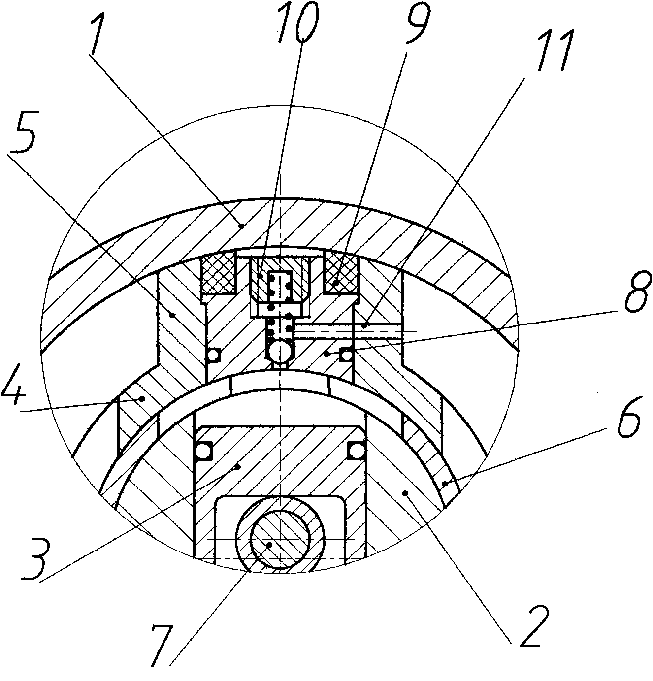
[0024] Figure 5 is an embodiment of the invention - a radial piston pump with double supported eccentric shafts 7 and double pistons 3, Image 6 for Figure 5 The B-B section view.

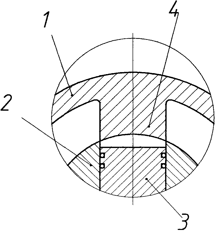
[0025] The figure shows pump body 1, rotor 2, piston 3, spacer tongue 4, spacer tongue sleeve 5, rotor sleeve 6, eccentric shaft 7, sealing compensation block 8, elastic pressure sleeve 9, discharge check valve 10, small channel 11 , pump cover 12, bearing 13, shaft seal device 14, motor 15, rolling ring 16, eccentric wheel 17.

[0026] In this example, a rotatable double-supported eccentric shaft 7 is adopted. One end of the eccentric shaft 7 is supported in the eccentric hole on the pump cover 12, and the other end is supported in the eccentric hole of the eccentric wheel 17 through the long groove of the waist of the piston 3. The eccentric wheel 17 is loosely installed in the inner cavity of the rotor 2 and is coaxial with it, and a rolling ring 16 is installed at the hinge joint between t...


PUM


Abstract

The invention relates to a small-flow high-lift radial piston pump, which is mainly formed by a pump body, a pump cover, a piston, a rotor, an eccentric shaft and a motor. A rotor bushing is fixedly installed on the external circle of the rotor. A radial hole with smaller diameter which is coaxial with the radial through hole of the rotor is arranged on the rotor bushing. Narrow grooves which are communicated with the radial through hole are arranged on the two sides of the radial hole. A volute tongue bushing is installed in the pump body. A sealing compensation block is installed in the volute tongue of the volute tongue bushing. A discharge check valve is arranged in the sealing compensation block. The width of the volute tongue is larger than the width of a radial passage on the rotor bushing. By adopting the structure, the area and the length of the sealing surface of the clearance of the volute tongue are increased, the radial sealing clearance between the sealing compensation block and the rotor bushing is kept to be zero, the discharge pressure can be obviously improved and the goals of small flow and high lift are reached. Moreover, in combination with the advantages of an original rotor pump that the efficiency is high, the energy is saved, the self-absorption performance is superior, the runner is smooth and the pump can be used for delivering viscous liquid with fibrous or particle impurities and the like, and the application prospect of the small-flow high-lift radial piston pump is wide.

Description

technical field [0001] The invention relates to a positive displacement pump, especially a radial piston pump with small flow rate and high lift. Background technique [0002] Flow less than 10M 3 / h, small-flow high-lift pumps with a head greater than 100M are widely used in aerospace, chemical, pharmaceutical, metallurgy, and light industries. The types of pumps are multi-stage centrifugal pumps, high-speed centrifugal pumps, vortex pumps, and reciprocating pumps. Advantages and disadvantages. [0003] For centrifugal pumps, the specific speed of this small-flow high-lift pump is below 20, which is an ultra-low specific speed pump, and the efficiency is very low, generally below 30%. For example, QDLA vertical stainless steel multi-stage centrifugal pump, When the traffic is 0.6M 3 / h When the head is 100M, 12 stages of impellers need to be connected in series. When the head is 198M, 24 stages of impellers need to be connected in series. The efficiency is only 30%, and ...

Claims


Application Information

Patent Timeline
Patent Type & Authority Applications(China)
IPC IPC(8): F04C2/344F04C15/00
Inventor 余文凌
Owner 余文凌
Why Eureka
Try Eureka