Laser scanning imaging nondestructive inspection method for hot continuous casting blank surface defects

A laser scanning imaging and non-destructive testing technology, applied in the field of metallurgy, can solve the problems of inability to realize surface and near-surface defect morphology detection, difficult to identify scaly iron oxide scale, inability to detect defect depth information, etc., to improve the continuous casting process technology. , the effect of avoiding loss expansion and reducing production costs

Inactive Publication Date: 2010-10-27
CHONGQING UNIV
View PDF4 Cites 59 Cited by
  • Summary
  • Abstract
  • Description
  • Claims
  • Application Information

AI Technical Summary

Problems solved by technology

The biggest advantage of eddy current testing technology is that it can detect surface and near-surface defects, but affected by the skin effect and lift-off effect, eddy current and ultrasonic testing methods have poor accuracy, are greatly affected by iron oxide scale and defects, and cannot be realized. Detection of surface and near-surface defect morphology
The conventional optical inspection method has advantages in the detection of defects on the surface of high-temperature slabs, but it is difficult to identify the scaly iron scale that is not a defect itself but shows a certain defect image shape, even if some defects with relatively large sizes are detected, such as Wider transverse cracks, but because the depth information of the defects cannot be detected, the defects cannot be quantitatively evaluated
So far, there is no stable, accurate and reliable online detection system for surface defects of high-temperature slabs at home and abroad that can be applied to continuous casting industrial production lines

Method used


Image

  • Laser scanning imaging nondestructive inspection method for hot continuous casting blank surface defects
  • Laser scanning imaging nondestructive inspection method for hot continuous casting blank surface defects
  • Laser scanning imaging nondestructive inspection method for hot continuous casting blank surface defects

Examples


Embodiment Construction

[0020] The present invention will be described in further detail below in conjunction with the accompanying drawings.

[0021] The detection method of the present invention comprises the following steps:

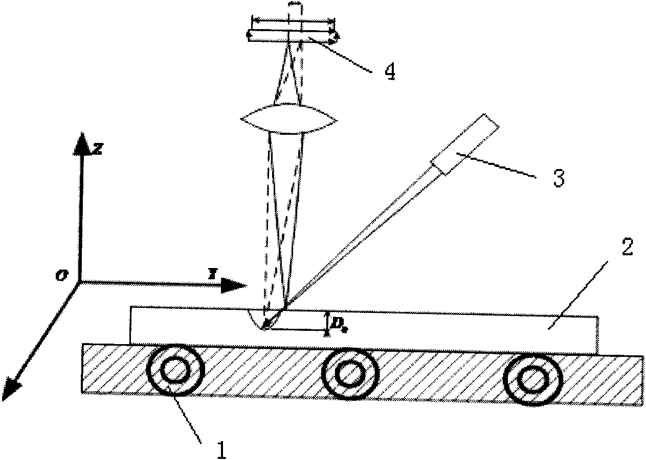
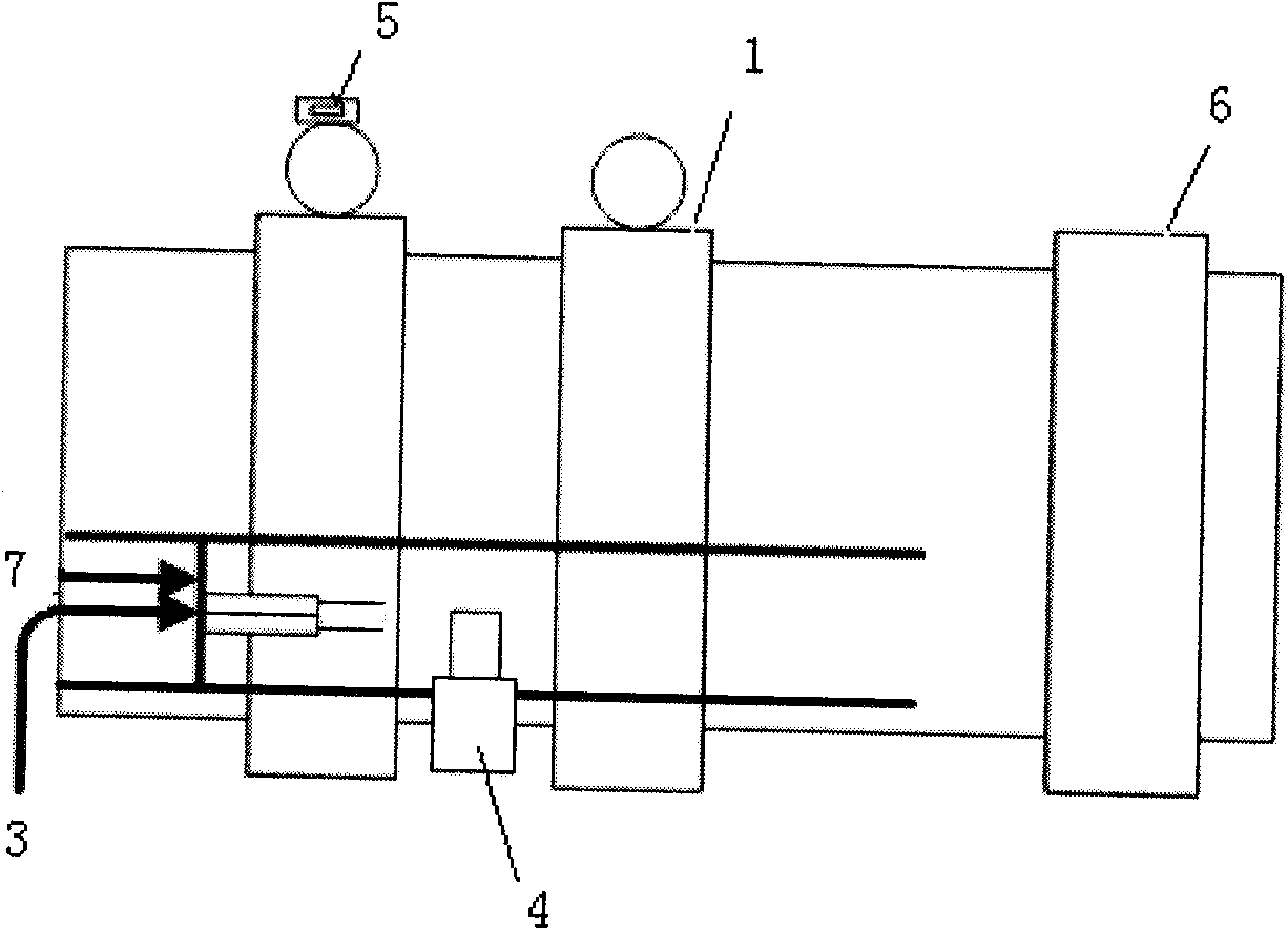
[0022] 1) Install a linear laser emitter above the high-temperature continuous casting slab. The linear laser emitter is installed in a high-temperature protective cover. The linear laser emitter irradiates the slab with laser light in the transverse direction according to a certain emission angle, thereby generating a horizontal line of the slab. (narrow) laser beams;

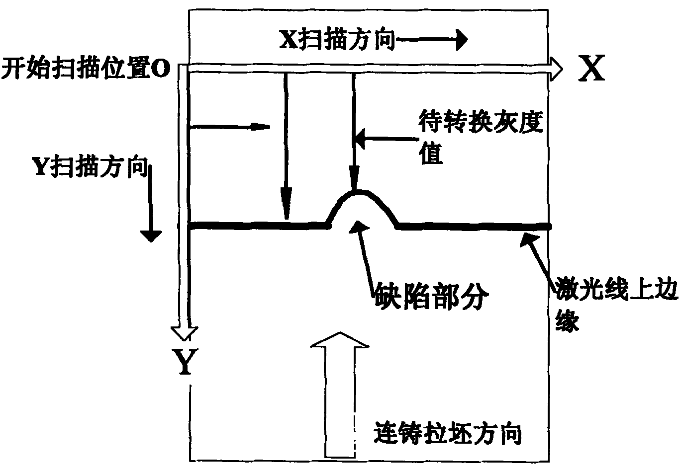
[0023] 2) The laser line beam is scanned by an area array CCD image sensor, and the scanning direction of the area array CCD image sensor is perpendicular to the surface of the high-temperature continuous casting slab and the laser line beam;

[0024] 3) Using the triangular ranging principle to extract the defect depth information represented on the scanned laser beam, the depth information corresponds to ...


PUM


Abstract

The invention discloses a laser scanning imaging nondestructive inspection method for hot continuous casting blank surface defects, comprising the following steps: 1) transversely irradiating a casting blank by a laser emitter to obtain a laser line; 2) scanning the laser line by utilizing an area array CCD image sensor; 3) extracting information representing the defect depths from the laser line so as to obtain a one-dimensional distance dot matrix formed by assembling the defect depths of the casting blank at the transverse position; and 4) mapping the one-dimensional distance dot matrix into gray level images with different gray levels; 5) splicing the gray level images at different transverse positions of a hot blank so as to obtain a whole gray level image; and 6) identifying the defects on the surface of the casting blank and reconstructing a casting blank surface tri-dimensional topographic image. The intention can effectively inhibit interference from a flaky scale on the high temperature casting blank surface which is not a defect but presents a defect state and water films so as to avoid the pseudo-defects from influencing detection precision, accurately identify defect target images and realize quantized detection of the defect depths, thereby realizing online detection of the defect states and depths of the surface of the casting blank under a high temperature state.

Description

technical field [0001] The invention relates to the field of metallurgy, in particular to an on-line non-destructive quantitative detection method for the surface defect form and depth of high-temperature continuous casting slabs, and can also be applied to the detection of surface defects of strip steel, heavy rails, and high-speed rails and the precise detection of three-dimensional surface topography. Background technique [0002] Continuous casting slab hot delivery-direct rolling (CC-DR) is a rapidly developed metallurgical technology that combines the latest technologies in steelmaking, continuous casting and rolling. It has many advantages such as energy saving, high success rate and short production cycle. At present, although continuous casting technology is still improving, defects such as surface cracks on continuous casting slabs are still difficult to completely avoid. In order to ensure that steelmaking, continuous casting, and steel rolling can be produced ac...

Claims


Application Information

Patent Timeline
Patent Type & Authority Applications(China)
IPC IPC(8): G01N21/892G01B11/22
Inventor 欧阳奇赵立明陈登福温良英张立志李万宏
Owner CHONGQING UNIV
Why Eureka
Try Eureka