High-gain planar wide-frequency antenna

A wide-band antenna and high-gain technology, applied in the field of microwave technology, can solve problems such as low antenna gain and large antenna gain changes, and achieve the effects of low axial ratio, increased gain, high gain and gain

Inactive Publication Date: 2010-10-27
UNIV OF ELECTRONICS SCI & TECH OF CHINA
View PDF2 Cites 19 Cited by
  • Summary
  • Abstract
  • Description
  • Claims
  • Application Information

AI Technical Summary

Problems solved by technology

[0003] At present, the length of the ordinary cavity-backed helical antenna changes the frequency-invariant characteristics of the helical antenna due to the length of the reflective cavity. Generally, the back cavity is filled with electromagnetic absorbing materials to reduce the resonance effect, so that the energy in the direction of the antenna back cavity will be absorbed. The wave material absorbs and converts it into heat energy release. Although the non-frequency effect of the helical antenna is realized, the antenna gain is very low due to the loss caused by the wave-absorbing material, and the antenna gain varies greatly within the entire bandwidth.

Method used


Image

  • High-gain planar wide-frequency antenna
  • High-gain planar wide-frequency antenna
  • High-gain planar wide-frequency antenna

Examples


Embodiment Construction

[0019] see Figure 1~5 .

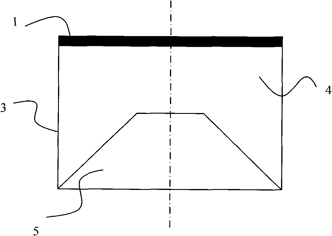
[0020] The working principle of the present invention is: microwave energy is fed from the signal source to the Archimedes spiral antenna radiation piece 1 through the microstrip gradient balun 2, the radiation piece produces forward radiation and back radiation, and the electromagnetic signal of the back radiation passes through the special-shaped The reflection cavity 4 reflects back the forward radiation, and superimposes with the original forward radiation signal, thereby increasing the energy of the forward radiation and increasing the gain of the antenna.

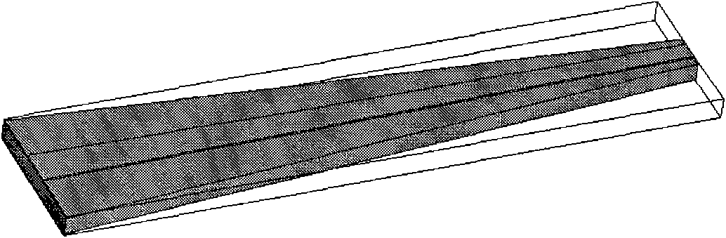
[0021] The present invention is composed of an Archimedes spiral antenna radiator 1, a casing 3, a gradual change balun 2 and a signal input end. There is a reflection cavity 4 inside the casing, and a reflection circular platform 5 is arranged in the reflection cavity 4. The outer surface of the circular platform is a reflection surface. . The inner wall of the reflection cavity 4 is cyli...


PUM


Abstract

The invention relates to a high-gain planar wide-frequency antenna which relates to a microwave technology and comprises an Archimedean spiral antenna radiation sheet, a tapered balun and a shell, wherein a reflection cavity is arranged in the shell, and the Archimedean spiral antenna radiation sheet is connected with a signal source accessing end through the tapered balun. The invention has the advantages that the gain of a wide-frequency spiral antenna is improved to a great degree, the circular polarization characteristic of far-field radiation is good, and meanwhile, the standing wave of the whole antenna system also has better performance. The invention has high gain, stable gain, lower axial ratio and wide application potential in the aspects of military affairs and civil use.

Description

technical field [0001] The present invention relates to microwave technology. Background technique [0002] The helical antenna itself can realize broadband and beam circular polarization, and is small in size, light in weight, and stable in structure. It has been widely used in the fields of anti-jamming and electronic countermeasures in satellite communications. In the field of modern antennas, the planar helical antenna with tilted beam pointing does not need to tilt the antenna plane to achieve the purpose of beam pointing to the satellite, and has a small size and low profile, so it has also attracted widespread attention as a ground mobile communication antenna. Planar broadband helical antennas have been mentioned in many literatures. However, the broadband helical antenna that realizes one-way high gain is still blank in China. [0003] At present, the length of the ordinary cavity-backed helical antenna changes the frequency-invariant characteristics of the helica...

Claims


Application Information

Patent Timeline
Patent Type & Authority Applications(China)
IPC IPC(8): H01Q1/36H01Q7/00H01Q19/10
Inventor 杨青慧张怀武刘颖力刘畅范丹
Owner UNIV OF ELECTRONICS SCI & TECH OF CHINA
Why Eureka
Try Eureka