Crane and controllable radiation system thereof

A heat dissipation system and radiator technology, applied in the direction of load suspension components, circuits or fluid pipelines, and the arrangement of cooling combination of power plants, etc., can solve the problems of not reaching the highest level, wasting power, and insufficient heat dissipation capacity, etc., and achieve a solution Waste of power and meet the heat dissipation requirements

Inactive Publication Date: 2010-11-03
XUZHOU HEAVY MASCH CO LTD
View PDF0 Cites 13 Cited by
  • Summary
  • Abstract
  • Description
  • Claims
  • Application Information

AI Technical Summary

Problems solved by technology

It can be seen that when the fan speed is at the highest point, the engine speed is the highest; and the most dangerous working point of the crane cooling system is often not at the maximum power point, but near the maximum torque point; The relationship curve is not a straight line, but a curve approximately in the form of a parabola; at the same time, if the gearbox has a retarder brake, the operating point of the retarder brake is generally within the range of the engine speed of 1000rpm-1700rpm, which just covers the engine speed. Maximum torque point; if the retarder brake is turned on, the power system is at the point of maximum heat dissipation power demand, but because the engine speed does not reach the highest point, that is, the heat dissipation system does not reach the maximum power point, which may easily cause insufficient heat dissipation
Therefore, when selecting radiator chips, if you refer to the heat dissipation power of the engine near the maximum torque point, a lot of power will be wasted when the engine is working at the rated speed; and if you refer to the heat dissipation power near the rated engine speed, it cannot meet the maximum engine performance. Cooling Requirements for Torque Operation
Adding an auxiliary radiator actually increases the heat dissipation area of ​​the heat dissipation system, and does not fundamentally solve the above problems

Method used


Image

  • Crane and controllable radiation system thereof
  • Crane and controllable radiation system thereof
  • Crane and controllable radiation system thereof

Examples


Embodiment Construction

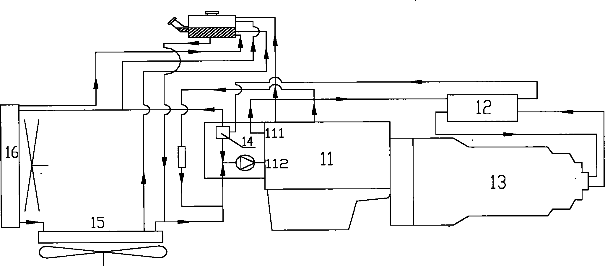
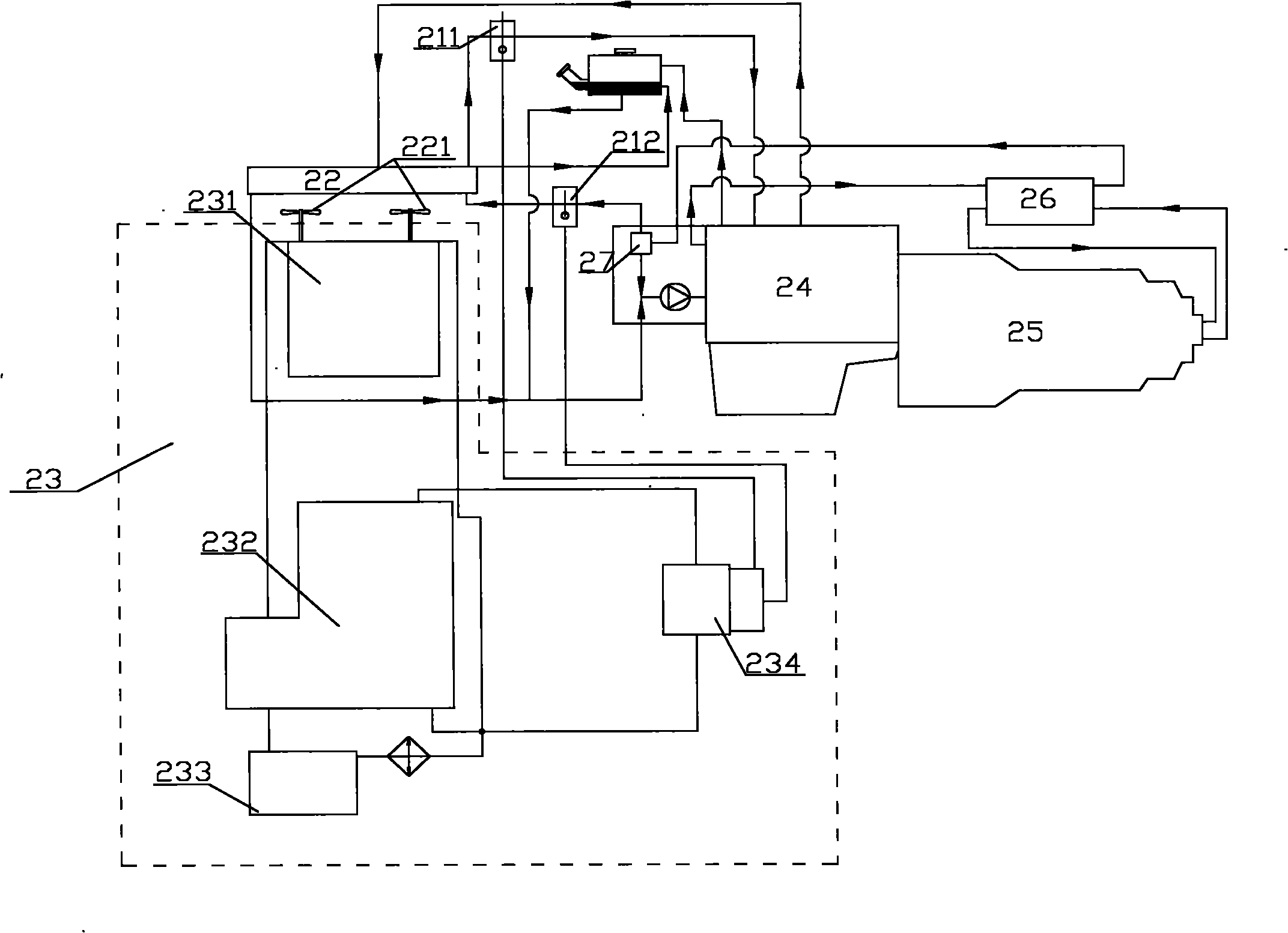
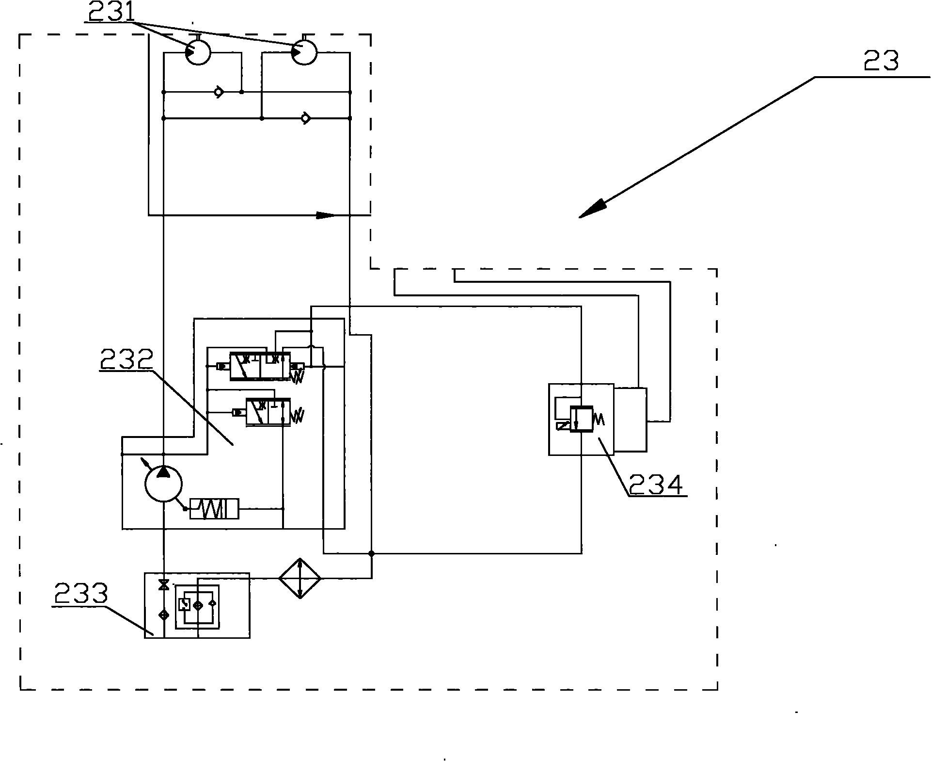
[0023] The core of the present invention is to provide a controllable heat dissipation system, which can change the heat dissipation power in real time according to different heat dissipation needs, thereby not only meeting the heat dissipation needs of the power system but also solving the problem of power waste. Another core of the present invention is to provide a construction machine including the above-mentioned controllable heat dissipation system.

[0024] In order to enable those skilled in the art to better understand the solution of the present invention, the present invention will be further described in detail below in conjunction with the accompanying drawings and specific embodiments.

[0025] Please refer to figure 2 , figure 2 It is a structural schematic diagram of a specific embodiment of the controllable heat dissipation system provided by the present invention.

[0026] A controllable heat dissipation system provided by a specific embodiment of the pres...


PUM


Abstract

The invention discloses a controllable radiation system, which comprises a main radiator in which a fan is arranged and a heat exchanger, wherein the water inlet of the heat exchanger is communicated with a coolant liquid outlet of an engine, and the water outlet of the heat exchanger is communicated with the coolant liquid return opening of the engine; and the radiator can be connected between the coolant liquid outlet and the coolant liquid return opening of the engine selectively. The system is mainly characterized in that: the fan is driven by a driving element which is powered by a power element; and the system also comprises a first temperature sensor for testing the temperature of the liquid in the coolant liquid return opening of the engine, a second temperature sensor for testing the temperature at the air outlet of the radiator and a control device for controlling the rotation speed of the driving element according to the temperature signals sent by the first temperature sensor and the second temperature sensor. The radiation power of the radiation system can be regulated according to the radiation amount required by a power system, so that the radiation power can be changed in real time according to work requirements. As a result, the radiation efficiency is improved and power waste is reduced.

Description

technical field [0001] The invention relates to the field of engineering machinery, in particular to a controllable heat dissipation system. In addition, the present invention also relates to a construction machine comprising the above-mentioned controllable heat dissipation system. Background technique [0002] With the rapid development of my country's economic construction, the market demand for cranes is increasing day by day. In the field of construction machinery, large-scale construction machinery, especially in cranes, due to the high power of the power system, the heat that needs to be dissipated will be relatively large, and natural cooling can no longer meet the requirements of the machinery, so the additional heat dissipation system is It is an indispensable part of every construction machinery, and the quality of the cooling system directly affects the quality of the whole machine. In large machinery, especially in cranes, due to the high weight of the whole m...

Claims


Application Information

Patent Timeline
Patent Type & Authority Applications(China)
IPC IPC(8): B60K11/04B60K11/06B60R16/02B66C13/00
Inventor 李丽吴高腾曹培雷朱长建刘东宏
Owner XUZHOU HEAVY MASCH CO LTD
Why Eureka
Try Eureka