Supercharge Your Innovation With Domain-Expert AI Agents!

Air energy heat pump water heater with ventilation function of cold air and fresh air

An air energy heat pump and fresh air ventilation technology, which is applied in the direction of fluid heaters, refrigeration and liquefaction, lighting and heating equipment, etc., can solve the problems of single function of air energy heat pump and waste of energy, etc., so as to improve indoor air quality and reduce dust , The effect of saving air conditioning energy consumption and operating costs

Inactive Publication Date: 2011-11-09
HARBIN INST OF TECH
View PDF0 Cites 0 Cited by
  • Summary
  • Abstract
  • Description
  • Claims
  • Application Information

AI Technical Summary

Problems solved by technology

[0003] The purpose of the present invention is to solve the problem of single function and waste of energy in the existing air energy heat pump, and further provide an air energy heat pump water heater with the functions of cooling air and fresh air

Method used


Image

  • Air energy heat pump water heater with ventilation function of cold air and fresh air
  • Air energy heat pump water heater with ventilation function of cold air and fresh air

Examples


specific Embodiment approach 1

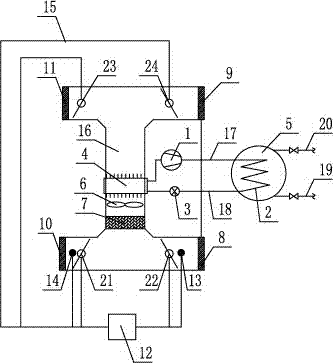
[0007] Specific implementation mode one: combine figure 1 Describe this embodiment, the air energy heat pump water heater with cold air and fresh air ventilation function of this embodiment is composed of a compressor 1, a sanitary hot water heat exchanger 2, a thermal expansion valve 3, a fin heat exchanger 4, and a hot water tank 5 , Axial fan 6, filter 7, the first window 8, the second window 9, the first filter 10, the second filter 11, the controller 12, the first temperature sensor 13, the second temperature sensor 14, Multiple signal lines 15, air pipe 16, first refrigerant pipe 17, second refrigerant pipe 18, tap water pipe valve 19, hot water pipe valve 20, first electric control valve 21, second electric control valve 22, second Three electric regulating valves 23 and a fourth electric regulating valve 24 are composed. The air pipe 16 is an I-shaped air pipe. A windshield 8 and a second windshield 9 are arranged up and down on the remaining two air outlet ends of th...

specific Embodiment approach 2

[0008] Specific implementation mode two: combination figure 1 The present embodiment will be described, and the filter 7 of the present embodiment is a nonwoven fabric filter. With such setting, the filtering effect is good, and the indoor air pollution is effectively reduced. Other compositions and connections are the same as in the first embodiment.

specific Embodiment approach 3

[0009] Specific implementation mode three: combination figure 1 The present embodiment will be described. Both the first windshield 8 and the second windshield 9 of the present embodiment are louvers. With such a setting, the air volume and direction can be controlled. Other compositions and connections are the same as those in Embodiment 1 or Embodiment 2.


PUM


Abstract

The invention relates to an air energy heat pump water heater with the ventilation function of cold air and fresh air, in particular to an air energy heat pump water heater solving the problems of single function and energy waste of a traditional air energy heat pump. The air energy heat pump water heater is characterized in that an air duct is an I-shaped air duct, a first filter screen and a second filter screen are respectively and vertically arranged at two air vent ends of the air duct, a first air window and a second air window are respectively and vertically arranged at the rest two air vent ends of the air duct, a fin heat exchanger, an axial flow fan and a filter are sequentially mounted in the vertical part of the air duct from top to bottom, a sanitary hot water heat exchanger is arranged in a hot water tank, the outlet end of the fin heat exchanger is connected with the inlet end of the sanitary hot water heat exchanger through a first refrigerant pipe, a compressor is mounted on the first refrigerant pipe, the inlet end of the fin heat exchanger is connected with the outlet end of the sanitary hot water heat exchanger through a second refrigerant pipe, and a thermal expansion valve is mounted on the second refrigerant pipe. The invention is particularly suitable for places needing preparing hot water for living and needing exchanging and refrigerating air by air conditioners.

Description

technical field [0001] The invention relates to an air energy heat pump water heater, in particular to an air energy heat pump water heater with the functions of cooling air and fresh air. Background technique [0002] Conventional air energy heat pumps have a single function and waste energy. Regardless of winter or summer, heat is taken from the outdoor air, and sanitary hot water is provided to the room through a heat pump device. For summer, the room has cooling needs and needs to remove heat from the room, while the air source heat pump water heater draws heat from the outdoor air to supply sanitary hot water. In this way, the cooling capacity in the process of preparing sanitary hot water by the air source heat pump water heater is wasted in vain. Moreover, in summer and transitional seasons, the amount of hot water is also large, and the wasted cooling capacity is considerable. For some places with a large amount of sanitary hot water, such as barber shops, recycli...

Claims


Application Information

Patent Timeline
Patent Type & Authority Patents(China)
IPC IPC(8): F25B29/00F24H4/04F24F1/00F24F13/28F24F7/06
Inventor 倪龙吕永鹏江辉民姚杨姜益强马最良
Owner HARBIN INST OF TECH
Features
  • R&D
  • Intellectual Property
  • Life Sciences
  • Materials
  • Tech Scout
  • Unparalleled Data Quality
  • Higher Quality Content
  • 60% Fewer Hallucinations
Learn More