Pulse radiating field time-space resolution measuring system based on optical fiber beam

A measurement system, time-space resolution technology, applied in the field of detector systems, can solve problems such as small dynamic range and low sensitivity, and achieve the effects of reducing signal distortion, improving sensitivity, and improving signal uniformity

Inactive Publication Date: 2010-11-03
NORTHWEST INST OF NUCLEAR TECH
View PDF0 Cites 7 Cited by
  • Summary
  • Abstract
  • Description
  • Claims
  • Application Information

AI Technical Summary

Problems solved by technology

[0005] The object of the present invention is to provide a pulsed radiation field time-space resolution measurement system based on fiber optic bundles, which solves the technical problems of low sensitivity and small dynamic range of existing time-space resolution measurement methods

Method used


Image

  • Pulse radiating field time-space resolution measuring system based on optical fiber beam
  • Pulse radiating field time-space resolution measuring system based on optical fiber beam
  • Pulse radiating field time-space resolution measuring system based on optical fiber beam

Examples


Embodiment Construction

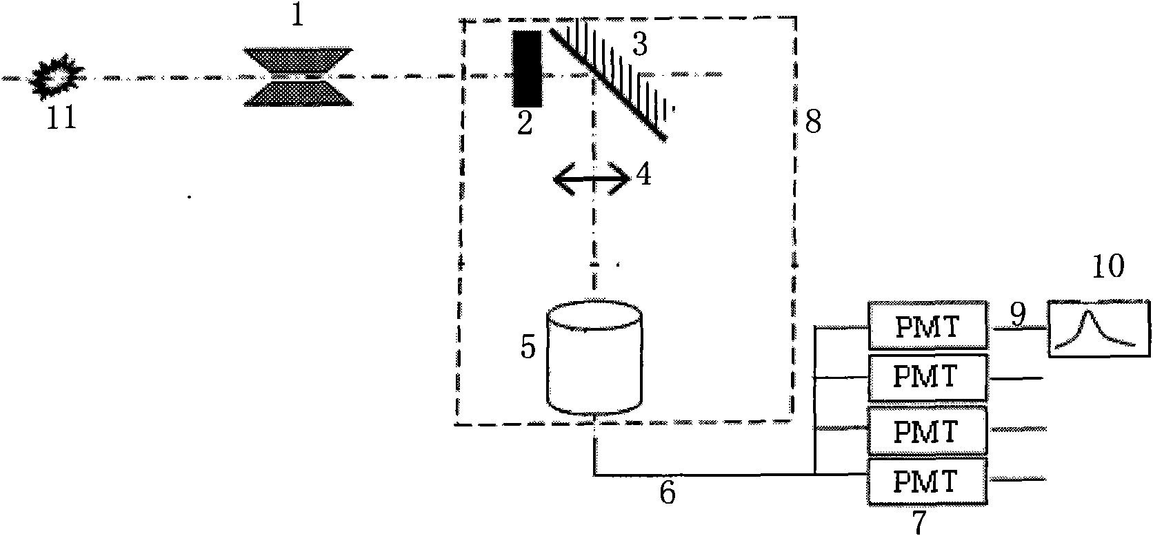
[0025] The pulsed radiation field time-space resolution measurement system based on optical fiber bundles of the present invention includes a thick pinhole 1, a scintillator 2, an optical system, an optical fiber bundle array 5, a transmission optical cable 6, a photodetector 7 and an oscilloscope 10; the optical system includes an optical box 8 and the reflector 3 and the coupling lens 4 arranged in the optical box 8; the fiber bundle array 5 is made up of the signal receiving end 61 of the transmission optical cable 6 arranged on the pin body 51 and the pin body 51; the scintillator 3 receives The ray passing through the thick pinhole 1 emits visible light, the reflector 3 reflects the light emitted by the scintillator and images it to the fiber bundle array 5 through the coupling lens 4, and the optical signal of the fiber bundle array 5 is transmitted to the optical fiber bundle array 5 through the transmission cable 6 Describe the photodetector 7, the detector 7 converts t...


PUM


Abstract

The invention relates to a pulse radiating field time-space resolution measuring system based on an optical fiber beam, which comprises a thick pinhole (1), a scintillator (2), an optical system, an optical fiber beam array (5), a transmission optical cable (6) and a photoelectric detector (7). The invention solves the technical problems of low sensitivity and small dynamic range of the traditional time-space resolution measuring way, improves the sensitivity of the system, can realize the output of signals with different strengths and achieve the aims of range division and improvement of dynamic range of the system and has convenient maintenance and processing and free distribution.

Description

technical field [0001] The invention relates to a detector system, in particular to a detector system suitable for time-space resolution measurement of a pulsed radiation field. Background technique [0002] For the measurement of pulsed radiation fields (neutrons, gamma rays, etc.), some of them need to know the changes of each point in the reaction zone with time. [0003] The main methods of time-space resolution are: framing camera and optical fiber time-space resolution measurement. The high-speed framing camera can continuously obtain multiple images of the reaction area at a certain interval, but this method has great limitations, mainly because the system has low sensitivity, limited application range, and the system has a small dynamic range, which is difficult to Covers the entire development process of the signal. If multiple channels are required, the system scale is too large, and maintenance and on-site debugging are very difficult. [0004] Optical fiber ti...

Claims


Application Information

Patent Timeline
Patent Type & Authority Applications(China)
IPC IPC(8): G01T1/20G01T3/06
Inventor 魏福利王培伟袁媛赵吉祯张美
Owner NORTHWEST INST OF NUCLEAR TECH
Why Eureka
Try Eureka