Compact matching type holographic aiming device optical system

An optical system and aiming device technology, applied in the field of holographic optical system, can solve the problems of height increase, poor laser coherence, unreachable, etc., and achieve the effect of reducing weight and ensuring aiming accuracy

Active Publication Date: 2010-11-03
刘守 +1
View PDF4 Cites 7 Cited by
  • Summary
  • Abstract
  • Description
  • Claims
  • Application Information

AI Technical Summary

Problems solved by technology

In the development of the holographic sight, there are two points of most concern: 1. The sight must be small in size and light in weight; 2. The holographic image used for aiming must be clear, and its direction cannot change with temperature during use
[0004] The sight disclosed in Chinese patent ZL200420074252.0, because the optical system is very simple, although it can be made small and light, it cannot meet the second requirement above. The reasons are: (1) during the use of the sight, the LD The temperature rise causes the output wavelength to change, causing the position of the holographic image to change; (2) The laser coherence emitted by the LD is poor, which makes the aberration of the hologram very large, so the holographic image is not clear
Chinese patent 200810071050.3 uses a mirror to make the laser beam folded to reduce the length of the optical system, but this folded optical path increases the height of the entire system
However, none of them can completely eliminate the positional variation of the holographic image with wavelength drift, so precise aiming cannot be achieved

Method used


Image

  • Compact matching type holographic aiming device optical system
  • Compact matching type holographic aiming device optical system
  • Compact matching type holographic aiming device optical system

Examples


Embodiment Construction

[0016] The following embodiments will further illustrate the present invention in conjunction with the accompanying drawings.

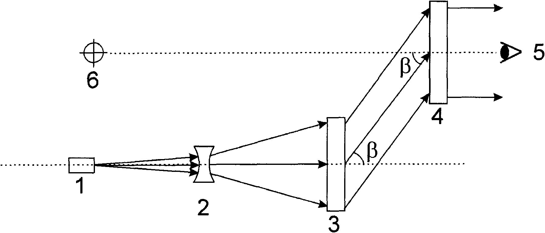
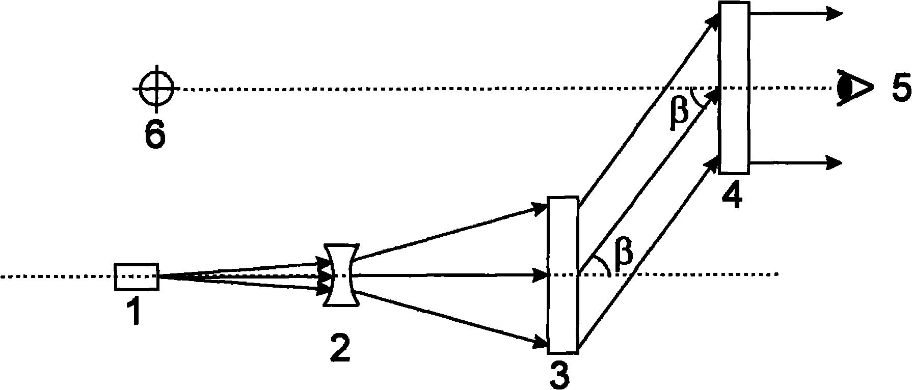
[0017] see figure 1 , the embodiment of the present invention is provided with: a laser diode (LD) 1, a concave lens 2, a transmission holographic matching element 3 and a transmission hologram 4.

[0018] Laser diode 1 is used to emit red visible light waves to provide light source for the system. The laser beam emitted by the laser diode 1 is divergent light, and the central light of the divergent light is in the horizontal direction.

[0019] The concave lens 2 is used to further expand the divergence angle of the divergent light emitted by the laser diode 1, so that the laser beam can reach the required beam area in a short running distance. The concave lens 2 is placed vertically in front of the laser diode 1, and the center point of the concave lens 2 It is on the same horizontal line as the central ray of the beam emitted by the laser diode 1...


PUM


Abstract

The invention provides a compact matching type holographic aiming device optical system, which relates to a holographic optical system. The compact matching type holographic aiming device optical system has compact structure, and can realize accurate aiming in any condition. The compact matching type holographic aiming device optical system is provided with a laser diode, a concave lens, a transmission-type holographic matching element and a transmission-type hologram, wherein the concave lens is perpendicularly arranged in front of the laser diode; the transmission-type holographic matching element is perpendicularly arranged in rear of the concave lens; the laser diode, the concave lens and the transmission-type holographic matching element are arranged on the same optical axis; and the transmission-type hologram is arranged on the upper rear of the transmission-type holographic matching element.

Description

technical field [0001] The present invention relates to a holographic optical system, in particular to a compact matching holographic collimator optical system for a holographic collimator device. Background technique [0002] The holographic sight uses the reproduced holographic virtual image to aim, which has the advantages of fast aiming, high aiming accuracy, and is not affected by climate and environmental conditions. Holographic sights can be installed on various firearms. Because they have advantages over other types of sights in close-range gun battles, holographic sights have been highly valued by military departments of various countries in recent years. [0003] A holographic sight must contain a laser diode (LD) and a hologram. The laser emitted by the LD is irradiated on the hologram, and the human eye can see a holographic division image presented in the distance through the hologram, and use this image to aim at the target to be shot. In the development of t...

Claims


Application Information

Patent Timeline
Patent Type & Authority Applications(China)
IPC IPC(8): G02B23/14G02B5/32
Inventor 刘守
Owner 刘守
Why Eureka
Try Eureka