Exposing machine and exposing method thereof

An exposure machine and exposure chamber technology, applied in the field of exposure and development technology, can solve the problems of short bulb life, increased production cost, and increased bulb replacement frequency, etc.

Inactive Publication Date: 2012-05-16
E WAY TECH
View PDF0 Cites 1 Cited by
  • Summary
  • Abstract
  • Description
  • Claims
  • Application Information

AI Technical Summary

Problems solved by technology

[0007] However, such a design will make the structure of the overall exposure machine more complicated, and the body of the overall exposure machine will also become relatively larger; especially, it is necessary to use a bulb with a large wattage, and the life of a bulb with a large wattage is generally quite short. , not only increases the replacement frequency of bulbs, but also relatively increases the invisible production cost

Method used


Image

  • Exposing machine and exposing method thereof
  • Exposing machine and exposing method thereof
  • Exposing machine and exposing method thereof

Examples


Embodiment Construction

[0043] The features of the present invention can be clearly understood by referring to the detailed description of the drawings and embodiments of the present invention.

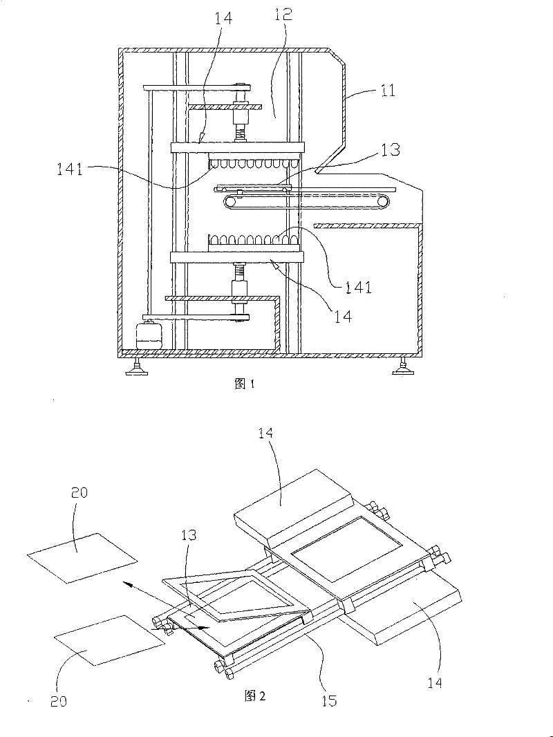
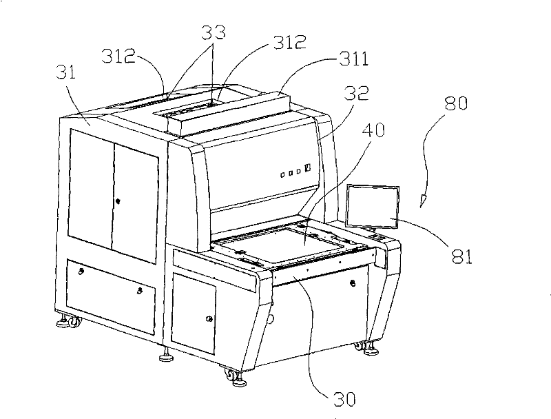
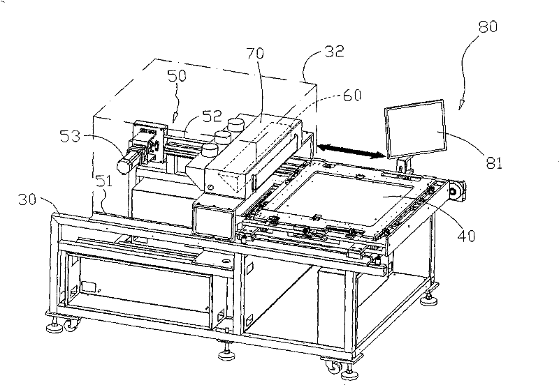
[0044] The present invention aims to provide an exposure machine that is less likely to generate heat accumulation and can relatively reduce equipment volume and cost, and an exposure method related thereto; the exposure method first generates at least one self-exposure inside an exposure chamber of the exposure machine The strip light source illuminated above the moving stroke of the platform or from the bottom of the moving stroke of the exposure platform toward the moving stroke of the exposure platform; and then equipped with the exposure platform of the exposure machine to receive the at least one strip light source in a way of relative displacement with the at least one strip light source at a predetermined speed. The irradiation of the light source further completes the exposure and development of the ...


PUM


Abstract

The invention discloses an exposing machine and an exposing method thereof. A strip light source irradiating towards the shift stroke of an exposing platform is at least generated at a position inside an exposing chamber relative to the upper part or the lower part of the shift stroke of the exposing platform; and the exposing platform receives the irradiation of the strip light source in a mode of relative displacement with the strip light source at a predetermined speed so that a processed object on the exposing platform finishes exposure and development. The number of bulbs can be greatly reduced, the volume of the integral exposing machine is relatively reduced, the equipment cost is reduced, and the heat concentration phenomenon of the exposing chamber is reduced; and in particular, the exposing platform passes through the exposing platforms in turn by adopting a mode of continuous cyclic conveying so as to promote the processing capacity of the exposing machine.

Description

technical field [0001] The utility model relates to an exposure and developing technology of an exposure machine, and aims to provide an exposure machine which is less likely to generate heat accumulation and can relatively reduce equipment volume and cost, and an exposure method related thereto. Background technique [0002] Generally speaking, when the printed circuit board or semiconductor chip is exposed to the development process, a layer of photoresist is first coated on the surface of the object to be processed, and then the circuit wiring pattern on the original is mapped to the surface of the object to be processed by the irradiation of the light source. On the photoresist layer, the chemical properties of the photoresist layer are changed due to the irradiation of the light source, and then the photoresist that has been irradiated by the light source or the unexposed photoresist is removed from the surface of the processed object by removing the photoresist. , to f...

Claims


Application Information

Patent Timeline
Patent Type & Authority Patents(China)
IPC IPC(8): G03B27/16G03B27/26G03B27/10
Inventor 吕金水钟政学
Owner E WAY TECH
Why Eureka
Try Eureka