Hot rolled strip laminar cooling device capable of controlling cooled strip shape

A laminar flow cooling device, hot-rolled strip technology, applied in metal rolling, manufacturing tools, metal rolling, etc., can solve the problems of small cooling rate, cooling asymmetry, cooling area is too long, etc., to achieve high safety , Prevent damage, strong adjustment ability

Inactive Publication Date: 2010-11-10
UNIV OF SCI & TECH BEIJING
View PDF5 Cites 27 Cited by
  • Summary
  • Abstract
  • Description
  • Claims
  • Application Information

AI Technical Summary

Problems solved by technology

In the cooling process, there are mainly three types of uneven cooling that can cause problems with the shape of the steel plate: severe uneven cooling in the transverse direction, asymmetrical cooling in the thickness direction, and uneven mixing of cooling in the transverse and thickness directions
The disadvantage is that the cooling rate is small, the cooling area is too long, and the process adaptability is not strong
The Chinese invention patent ZL 200620166942.8 in 2006 disclosed the "Laminar flow cooling device for hot-rolled strip" and the Chinese invention patent ZL 200720016078.8 in 2007 disclosed the "Laminar cooling device for medium and wide steel strip mills". The main feature is the turning mechanism, No description of its cooling capacity and cooling plate shape control ability

Method used


Image

  • Hot rolled strip laminar cooling device capable of controlling cooled strip shape
  • Hot rolled strip laminar cooling device capable of controlling cooled strip shape
  • Hot rolled strip laminar cooling device capable of controlling cooled strip shape

Examples


Embodiment Construction

[0034] Attached below Figure 1~5 , the present invention is described in detail as follows:

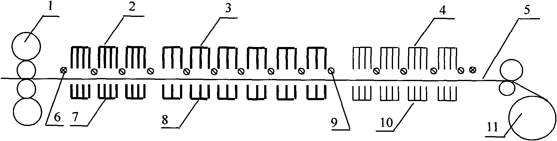
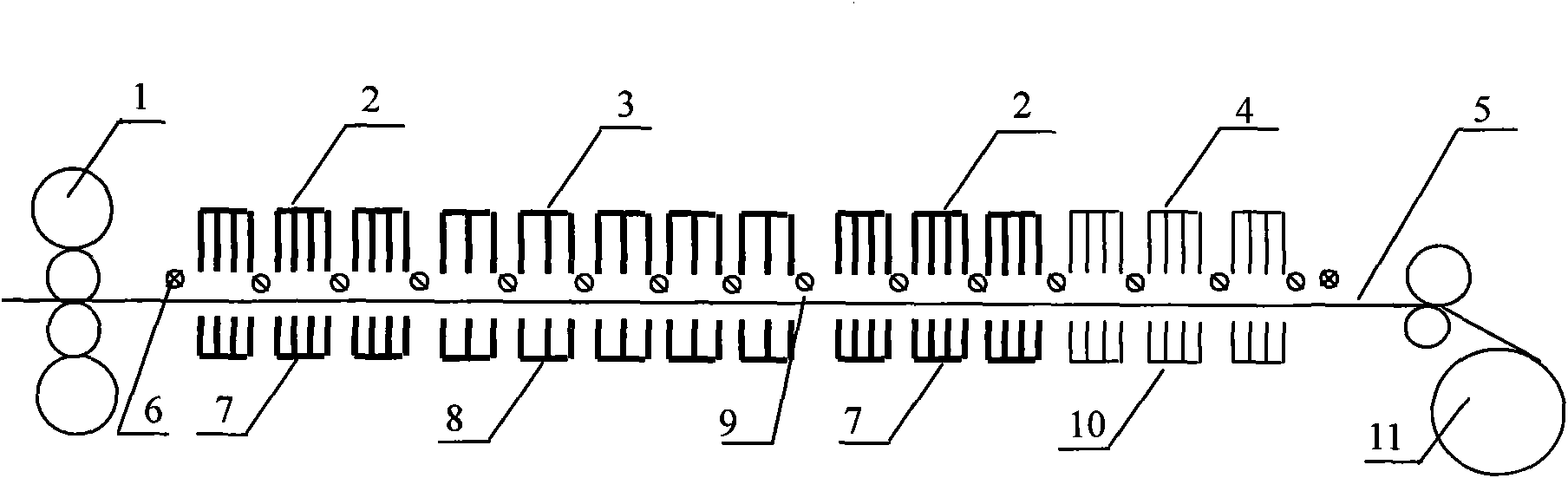
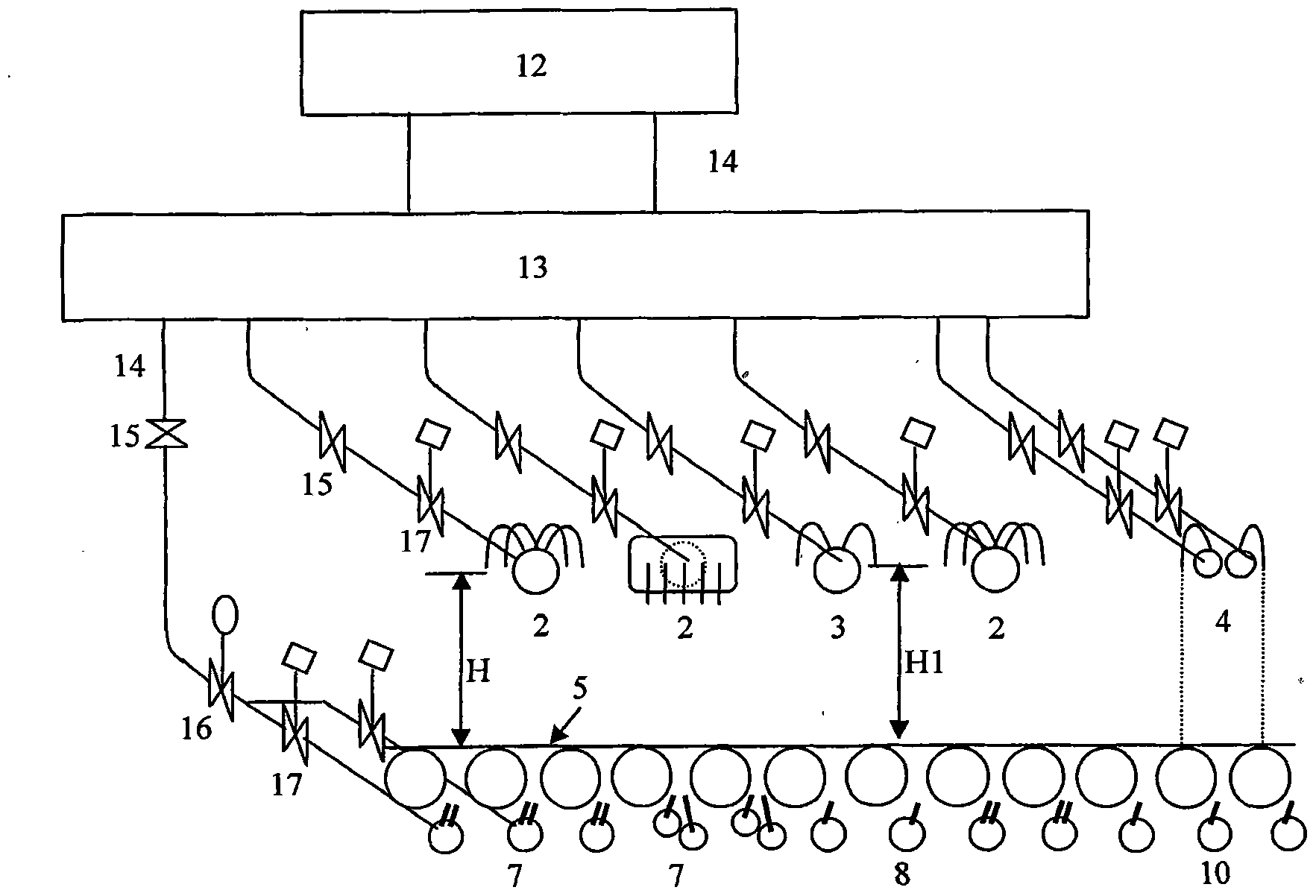
[0035] A laminar flow cooling device for hot-rolled strip steel with controllable cooling plate shape of the present invention consists of a high-level water tank 12, a water volume distributor 13, a high-density upper header 2, a high-density lower header 7, and a coarse-adjustment and fine-adjustment upper header 3 , 4 and the cooling zone composed of the lower headers 8 and 10 for coarse adjustment and fine adjustment. image 3 It is a connection schematic diagram of a laminar flow cooling device for hot-rolled strip steel with controllable cooling plate shape in the present invention. As shown in the figure, the pipeline 14, the manual valve 15, the flow regulating valve 16, and the pneumatic switch valve 17 respectively connect the water volume distributor 13 and high-density upper header 2, coarse adjustment upper header 3, fine adjustment upper header 4, water volume distribu...


PUM

PropertyMeasurementUnit
thicknessaaaaaaaaaa

Abstract

The invention provides a hot rolled strip laminar cooling device capable of controlling cooled strip shape. The device is arranged between a finishing mill and a coiling machine and is formed by a cooling area which is formed by a water distributor, a high-density upper header, an upper coarse adjustment header, an upper fine adjustment header, a high-density lower head, a lower coarse adjustment header, a lower fine adjustment header and a high-level water tank, wherein the water distributor is connected with the high-density upper header, the upper coarse adjustment header, the upper fine adjustment header, the high-density lower head, the lower coarse adjustment header and the lower fine adjustment header respectively through a pipeline, a hand valve, a flow regulating valve and a pneumatic on-off valve. The hot rolled strip laminar cooling device capable of controlling cooled strip shape is formed by a plurality of cooling sections which consist of one or two forced cooling sections Q, one coarse cooling section C and a fine cooling section J, wherein the forced cooling section Q is formed by a plurality of high-density upper header groups and high-density lower header groups; the coarse cooling section C is formed by an upper coarse adjustment header group and a lower coarse adjustment header group; and the fine cooling section J is formed by an upper fine adjustment header group and a lower fine adjustment header group. The invention has the advantages that the ultrafast cooling and the shape-controllable even cooling can be realized and the production needs of all kinds of commercial hot rolled strips and cold rolled base materials can be satisfied.

Description

technical field [0001] The invention belongs to the cooling technology for steel rolling production, in particular to a laminar flow cooling device for hot-rolled strip steel with controllable cooling plate shape. Background technique [0002] With the increasing demand for steel products in the market, the requirements for its quality are also getting higher and higher. Controlled cooling after rolling is a very effective method to improve the quality of steel plates and has been widely used. The basic principle of controlled cooling is to improve the structure and properties of the steel by controlling the cooling rate and final cooling temperature of the rolled steel plate. Its important purpose is to further increase the strength of the steel plate through controlled cooling, and at the same time, by using the relationship between the alloy elements of the steel and the cooling rate after rolling, the steel with the same composition can be used to produce products with ...

Claims


Application Information

Patent Timeline
Patent Type & Authority Applications(China)
IPC IPC(8): B21B45/02
Inventor 余伟邓宏玉詹智敏张立杰韩爽高英杰何春雨刘涛徐言东程知松
Owner UNIV OF SCI & TECH BEIJING
Why Eureka
Try Eureka