
Wind-assisted braking system for automobile

A technology for auxiliary braking and automobiles, which is applied in the directions of brakes, braking components, vehicle components, etc., can solve the problems of high manufacturing cost, reduce the use space of the vehicle body, and increase the maintenance cost, and achieve low manufacturing cost, reliable operation and simple structure. Effect

Inactive Publication Date: 2012-01-11
尹梦晨
View PDF1 Cites 0 Cited by
  • Summary
  • Abstract
  • Description
  • Claims
  • Application Information

AI Technical Summary

Problems solved by technology

However, the motor vehicle wind brake plate has the following obvious defects: (1) the mechanism is too complicated, regardless of its working reliability, the complexity of the mechanism means that the manufacturing cost will be quite high, and the maintenance cost will also increase accordingly; (2) ) The multiple drums and wire ropes set will greatly reduce the space used inside the car body, and may interfere with the functions and layout of the roof sunroof and the trunk; (3) According to its description, the aerodynamic resistance of up to 300 kg is bound to affect the There is a huge strength requirement for the structure of the force point; moreover, the mechanism will be opened during each braking action, but it is not necessary when the motor vehicle is running at low speed; (4) while pursuing the braking effect, the aesthetics are ignored There is no aesthetic feeling at all, and it is necessary to add some supporting mechanisms that the original car did not have, such as the rear anti-roll wheel

Method used


Image

  • Wind-assisted braking system for automobile
  • Wind-assisted braking system for automobile
  • Wind-assisted braking system for automobile

Examples


Embodiment Construction

[0019] The present invention will be further described below in conjunction with drawings and embodiments.

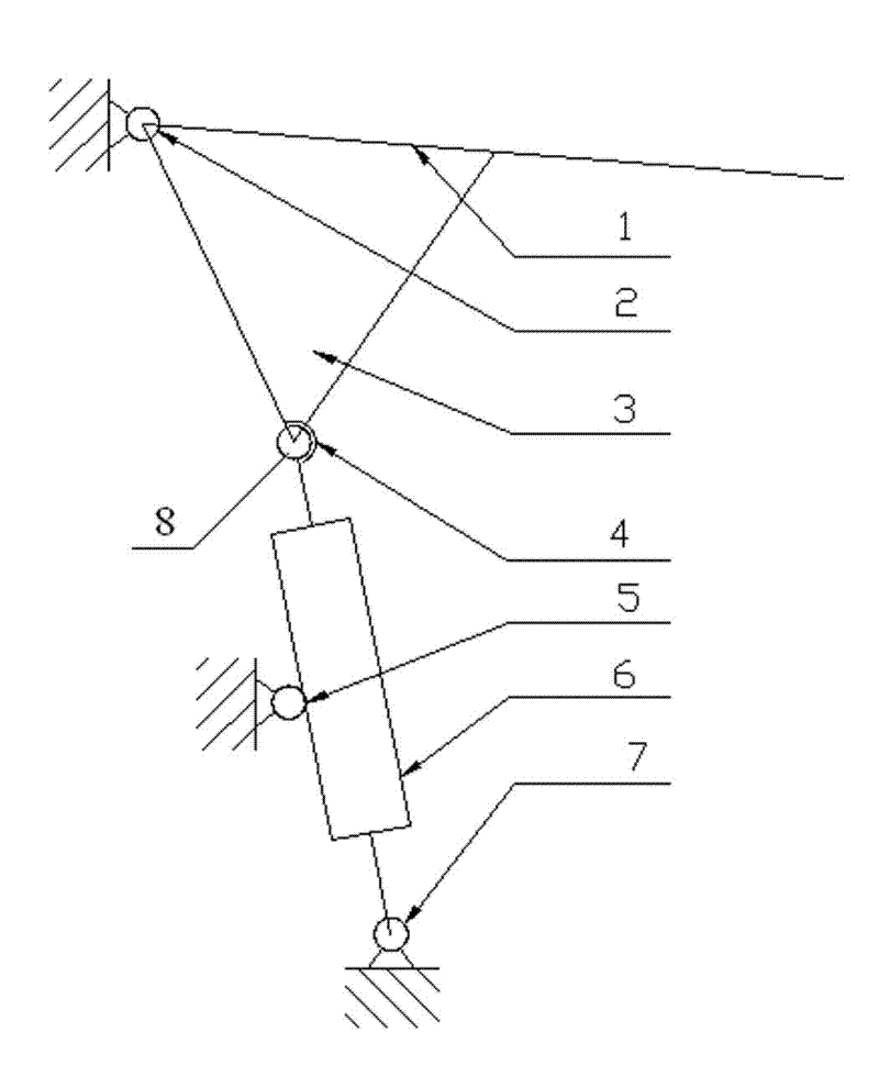
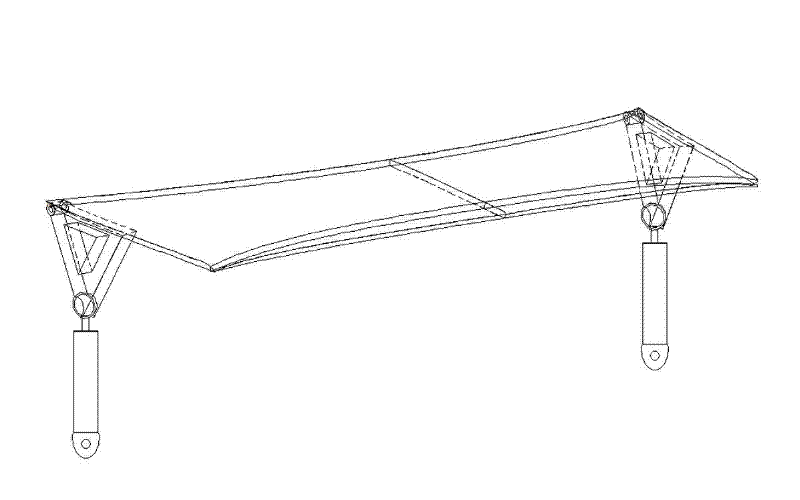
[0020] With reference to the accompanying drawings, this embodiment includes an auxiliary brake flap 1 hidden on the trunk of the car, one end of the auxiliary brake flap 1 is hinged on the lower frame of the rear windshield of the car, and the two sides of the auxiliary brake flap 1 are Fixed on two triangular brackets 3, one side of the triangular bracket 3 is fixedly connected with the auxiliary brake wing 1, the auxiliary brake wing 1 and the triangular bracket 3 share the hinge point I2 with the trunk cover of the car, and are connected with the auxiliary brake wing The hemispherical socket 4 on one corner of the triangular bracket 3 opposite to the plate 1 is connected with the ball head 8 at one end of the piston of the hydraulic cylinder 6, and the lower part of the hydraulic cylinder 6 is fixed and hinged to the bottom of the trunk through the hinge point II7. ...


PUM


Abstract

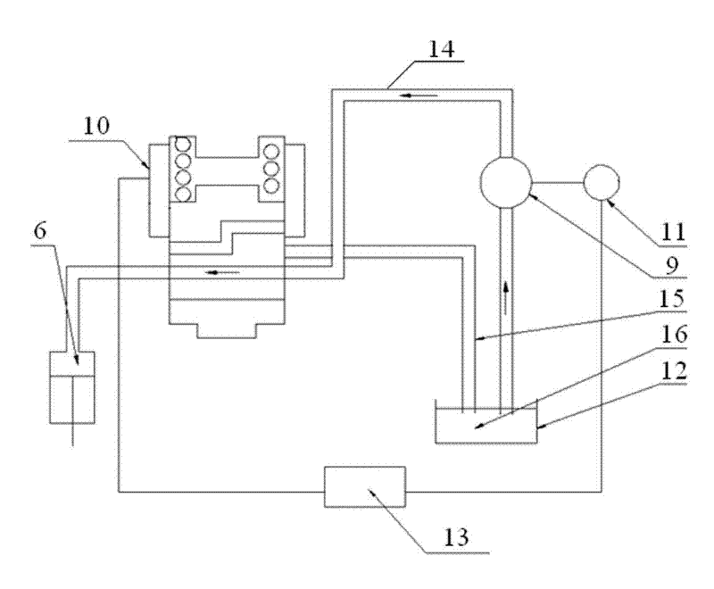
The invention provides a wind-assisted braking system for an automobile. The system comprises an auxiliary braking wing plate hidden on a trunk of the automobile, wherein one end of the auxiliary braking wing plate is hinged on a lower frame of a back windshield of the automobile; both sides of the auxiliary braking wing plate are fixed to two triangular brackets; one side of each triangular bracket is fixedly connected with the auxiliary braking wing plate; the auxiliary braking wing plate and the triangular brackets share a hinge point I with a cover plate of the truck of the automobile; a hemispherical cavity on a corner of the triangular bracket opposite to the auxiliary braking wing plate is connected with a ball head at one end of a hydraulic cylinder piston; the lower part of a hydraulic cylinder is hinged at the bottom of the trunk through a hinge point II; the hydraulic cylinder is connected with an oil path which is branched from a pressure accumulator and is provided with an electromagnetic valve for controlling closing of the oil path; the pressure accumulator is connected with an electric hydraulic pump of an anti-lock braking system (ABS) of the automobile and connected with a hydraulic oil tank through the oil path; and the electromagnetic valve is connected with a controller of the ABS of the automobile and directly leads to the hydraulic oil tank through a reflux oil path. The system has the advantages of simple structure, reliable work, small size and low manufacturing cost.

Description

technical field [0001] The invention relates to an automobile auxiliary braking system, in particular to a wind energy auxiliary braking system used for emergency braking of an automobile. Background technique [0002] Now that the automobile industry is highly developed, the brake deceleration system of the car is still realized by using the pure physical process of friction between the wheel and the ground and the brake, and the energy consumption is high. When the car is running fast, the braking is reliable. Sex is also poor. [0003] In Japan and Europe, aerodynamic braking technology has been successfully applied to the braking of trains. This braking method makes full use of wind energy, a clean, natural and environmentally friendly energy source, and the braking device has no wearing parts and no friction heat, so it has the characteristics of high reliability and low maintenance cost. Moreover, aerodynamic resistance is proportional to the square of the speed. The...

Claims


Application Information

Patent Timeline
Patent Type & Authority Patents(China)
IPC IPC(8): B60T1/16
Inventor 尹梦晨
Owner 尹梦晨
Learn More