Method for constructing fiber blanket protective layer for furnace
A construction method and technology of fiber blankets, which are applied in the field of kilns, can solve problems such as difficulty, unevenness of the protective plate, difficulty in adjusting and uniform density of fiber blankets, etc., and achieve the effect of simple construction, smooth surface and accurate positioning
- Summary
- Abstract
- Description
- Claims
- Application Information
AI Technical Summary
Problems solved by technology
Method used
Image
Examples
Embodiment 1
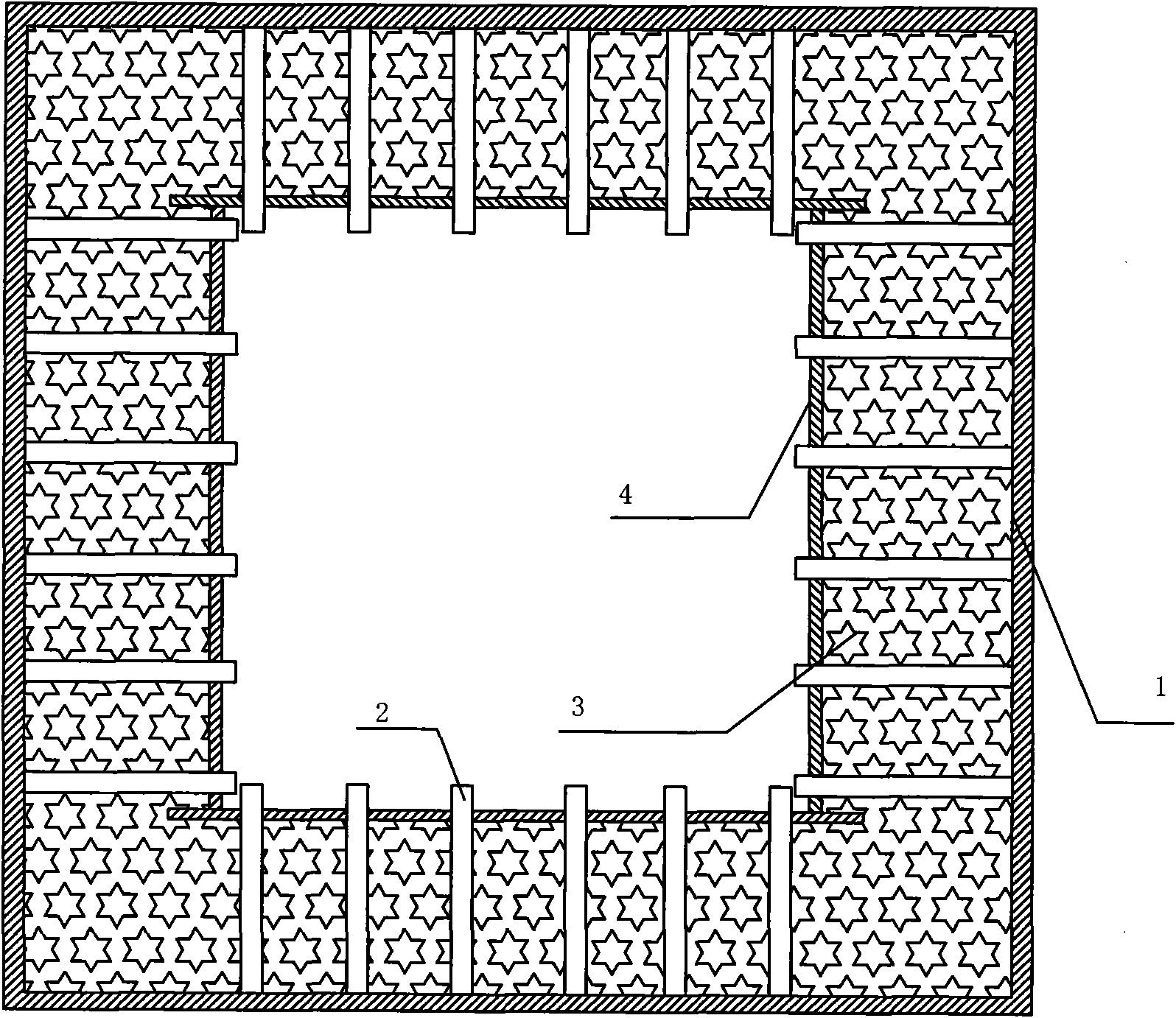
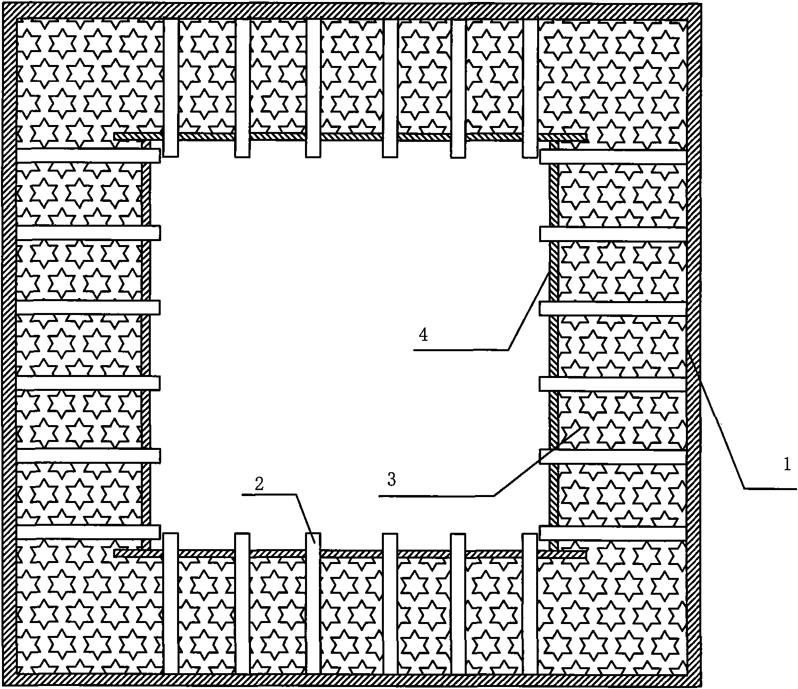
[0028] A kind of construction method of fiber blanket protective layer for kiln of the present invention adopts following construction steps:
[0029] The name of the furnace is silicon steel decarburization tunnel type continuous furnace. The size of the furnace shell is 1720mm×1800mm×88000mm, and the required materials for the fiber blanket protective layer of the furnace are: Q215 steel plate, ceramic fiber blanket, tie rod, casing and 0Cr25Ni20 stainless steel plate.
[0030] 1. Make the shell of the kiln first, and do not weld the top plate first; the furnace wall is made of 6mm Q215 steel plate;
[0031] 2. According to the requirement of tie rod spacing of 350mm×350mm, stake out on the inner wall of the kiln, and weld one end of the polished rods of several tie rods to the inner wall of the kiln; the overall length of the tie rods is greater than the total thickness of the fiber blanket: 20mm, and the material of the tie rods is 0Cr18Ni9 Stainless steel, total length: ...
Embodiment 2
[0039] The invention discloses a construction method of a fiber blanket protective layer for a kiln, and the required materials for the fiber blanket protective layer for a kiln include Q215 steel plate, ceramic fiber blanket, pull rod, casing and 0Cr25Ni20 stainless steel plate.
[0040] The name of the furnace is silicon steel magnesia baking tunnel type continuous furnace. The size of the furnace shell is 1670mm×1750mm×64000mm,
[0041] Tie rod: The material of the pull rod is 0Cr18Ni9 stainless steel, the total length: 320mm, one end of the pull rod is a polished rod, the other end is a screw, the specification of the threaded part of the screw is: M6×30mm, the diameter of the tie rod: 6mm, the distance between the tie rods: 400mm×400mm; the whole of the tie rod The length is greater than the total thickness of the fiber blanket: 20mm.
[0042] Ceramic fiber blanket insulation layer thickness: 300mm;
[0043] Casing inner diameter: 7mm, outer diameter 10mm, wall thicknes...
Embodiment 3
[0046] The invention discloses a construction method of a fiber blanket protective layer for a kiln. The required materials for the fiber blanket protective layer for a kiln include: 8mm Q215 steel plates for the furnace wall; ceramic fiber blankets, pull rods, casing pipes and 0Cr25Ni20 stainless steel plates.
[0047] The name of the kiln is insulating coating coating and baking tunnel type continuous furnace. The size of the furnace shell is 1770mm×1850mm×64000mm.
[0048] Tie rod: The material of the tie rod is 0Cr18Ni9 stainless steel, the total length: 420mm, one end of the tie rod is a polished rod, the other end is a screw, the screw thread length: M8×30mm, the diameter of the tie rod: 8mm, the distance between the tie rods: 300mm×300mm; the overall length of the tie rod is larger than the fiber Total blanket thickness: 20mm.
[0049] Ceramic fiber blanket insulation layer thickness: 400mm;
[0050] Casing inner diameter: 7mm, outer diameter 11mm, wall thickness: 2mm;...
PUM
| Property | Measurement | Unit |
|---|---|---|
| thickness | aaaaa | aaaaa |
| thickness | aaaaa | aaaaa |
| thickness | aaaaa | aaaaa |
Abstract
Description
Claims
Application Information
 - R&D
- Intellectual Property
- Life Sciences
- Materials
- Tech Scout
- Unparalleled Data Quality
- Higher Quality Content
- 60% Fewer Hallucinations
Browse by: Latest US Patents, China's latest patents, Technical Efficacy Thesaurus, Application Domain, Technology Topic, Popular Technical Reports.
© 2025 PatSnap. All rights reserved.Legal|Privacy policy|Modern Slavery Act Transparency Statement|Sitemap|About US| Contact US: help@patsnap.com


