
Illumination layout simulation method and system

A simulation method and layout technology, applied in the field of simulation systems, can solve problems such as hindering the application and promotion of new light sources, costing a lot of money, and difficulty, and achieving the effect of helping to expand business, reducing research and development costs, and improving installation efficiency.

Inactive Publication Date: 2010-11-10
ZHUHAI JINGYING ENERGY SAVING
View PDF0 Cites 11 Cited by
  • Summary
  • Abstract
  • Description
  • Claims
  • Application Information

AI Technical Summary

Problems solved by technology

These new electric light sources have many shapes and specificities, and can no longer be simply regarded as point light sources or line light sources. When designing a lighting system, how to combine these new electric light sources with different shapes is very difficult. It is more difficult to design reflective parts (such as reflectors) or refractive parts (such as refractive lenses) for light sources. It often requires multiple trial production experiments and consumes a lot of money to finally finalize the shape, which seriously hinders the application and promotion of new light sources.

Method used


Image

  • Illumination layout simulation method and system
  • Illumination layout simulation method and system
  • Illumination layout simulation method and system

Examples


Embodiment approach 1

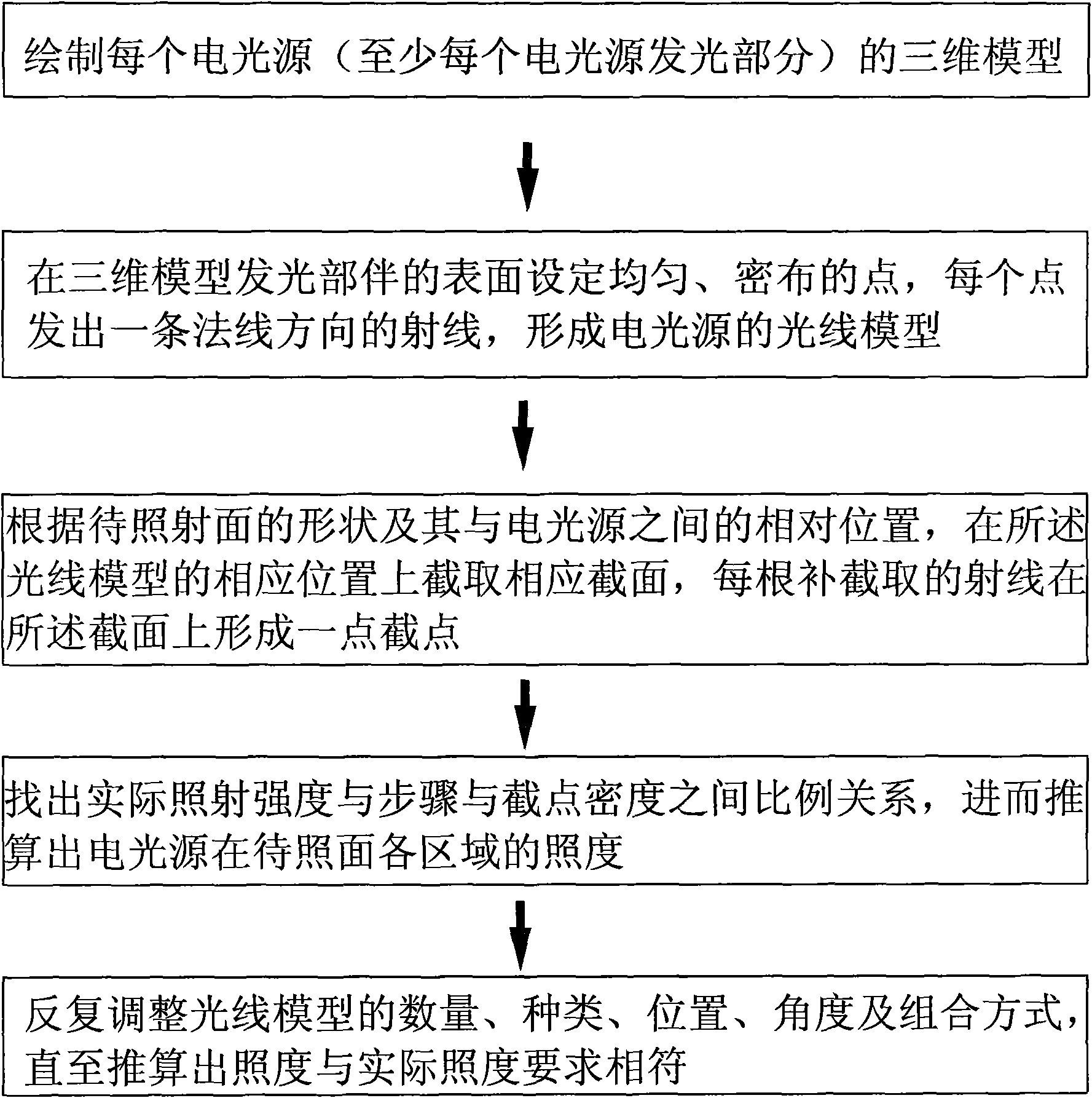
[0032] Implementation mode one: if Figure 1-3 As shown, the lighting layout simulation method includes the following steps:

[0033] ①. Draw a three-dimensional model for each electric light source—at least for the light-emitting part of each electric light source;

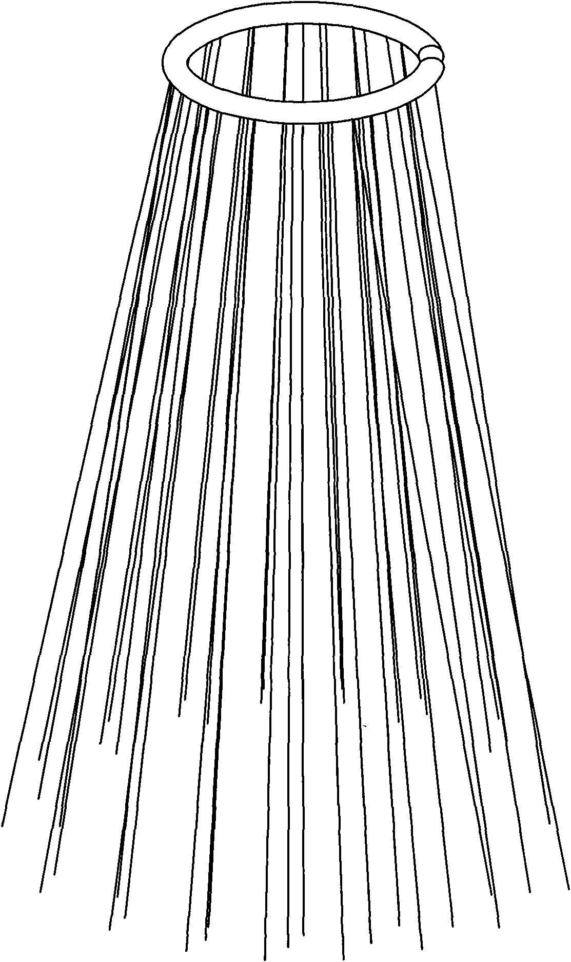
[0034] ②. Set uniform and dense points on the surface of the light-emitting part of the three-dimensional model, and set a ray outward along the normal direction from each point. All the rays constitute the light model of the electric light source. For example, the 3D model of the light-emitting part of the ring-shaped energy-saving lamp and its light model, such as figure 2 shown.

[0035] ③, according to the shape of the surface to be irradiated (not limited to the plane) and its relative position with the electric light source, intercept the corresponding section at the corresponding position of the light model, and each intercepted ray forms a Intercept point, where the cross-sectional shape and position ...

Embodiment approach 2

[0041]Embodiment 2: The illumination layout simulation system includes a database and a cross-section interception device, wherein the database stores three-dimensional models of various electric light sources, at least three-dimensional models of light-emitting parts of various electric light sources are stored, and the surface of the light-emitting part of the three-dimensional model is set Set uniform and densely distributed points, and start from each point, set a ray outward along the normal direction; all rays constitute the ray model of the electric light source, and the section intercepting device is based on the relative relationship between the surface to be irradiated and the electric light source. position, a cross-section at a corresponding position of the light model, and its cross-sectional shape corresponds to the shape of the surface to be irradiated. It is also equipped with a light model adjustment device, which is used to adjust the quantity, type, position,...


PUM


Abstract

The invention relates to illumination layout simulation method and system. The prior art has no simulation design method and system for an illumination system. Accordingly, the illumination layout simulation method comprises the following steps of: 1, drawing a three-dimensional model for each electric light source, at least for the luminescence part of each electric light source; 2, setting uniform and dense points on the surface of the luminescence part of each three-dimensional model, and setting radials outwards from each point along a normal direction, wherein a light ray model of the electric light source is formed by all the radials; and 3, intercepting a corresponding section on the corresponding position of the light ray model according to the shape of a surface (which is not limited to be plane) to be illuminated and a relative position between the surface to be illuminated and the electric light source, wherein a cutoff point is formed on the section by each intercepted radial, and the shape and the position of the section correspond to the surface to be illuminated. The invention can provide real-time, cheap and accurate guidance for illumination designs and is suitable for various lamp enterprises and design and production units of the illumination systems.

Description

technical field [0001] The invention relates to a simulation system, in particular to a lighting layout simulation method and system. Background technique [0002] When people carry out the overall design of the lighting system, they simply regard traditional electric light sources such as incandescent lamps, mercury lamps, sodium lamps, and metal halide lamps as point light sources or line light sources. They are all used in occasions where light distribution requirements are not high. [0003] With the continuous improvement of people's awareness of environmental protection and energy saving, people put forward higher requirements for control design. Take street lights as an example: In the past, people only required street lights to be bright enough, and often used words such as "bright lights, like daytime" to describe the bustling scene of the city; It will also cause light pollution; if the irradiation intensity is small, passers-by will not be able to see the road c...

Claims


Application Information

Patent Timeline
IPC IPC(8): G06F17/50
Inventor 肖斌刘伟赵永兵孙晓利
Owner ZHUHAI JINGYING ENERGY SAVING
Learn More