Curved path cutting method of brittle base plate by laser cutting

A brittle material substrate, laser cutting technology, applied in the direction of laser welding equipment, welding equipment, metal processing equipment, etc., can solve the problems of low cutting precision, crack propagation path is easy to deviate from laser movement, etc., and achieve high cutting precision.

Active Publication Date: 2012-11-14
苏州金盛瓷业有限公司
View PDF5 Cites 0 Cited by
  • Summary
  • Abstract
  • Description
  • Claims
  • Application Information

AI Technical Summary

Problems solved by technology

[0006] In order to overcome the disadvantages of the prior art that when the cutting path is not at the symmetrical position of the substrate or when the cutting path is a curve, the crack propagation path is easy to deviate from the laser moving track and the cutting accuracy is low, the present invention provides a method that can ensure the crack along the predetermined path. Cutting path extension, curvilinear path cutting method for laser cutting brittle material substrates with high cutting precision

Method used


Image

  • Curved path cutting method of brittle base plate by laser cutting
  • Curved path cutting method of brittle base plate by laser cutting
  • Curved path cutting method of brittle base plate by laser cutting

Examples


Embodiment 1

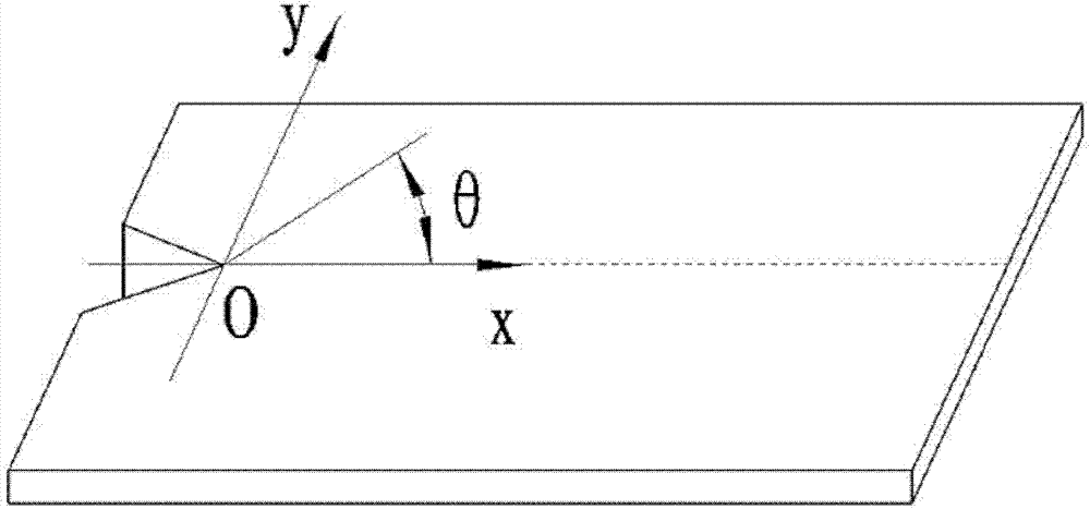
[0027] refer to figure 1 :

[0028] A curvilinear path cutting method for laser cutting a brittle material substrate, comprising the following steps:

[0029] 1. Create an initial crack on the substrate as a cutting path, and set sampling points on the cutting path based on experience; respectively obtain the cracking angle θ at each sampling point, and the cracking angle θ is the current expansion direction and the next moment the acute angle between the expansion directions;

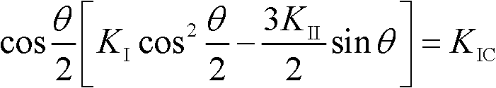
[0030] 2. Obtain the current sampling point, the cracking angle θ obtained from the current sampling point and the fracture toughness K of the substrate IC , to calculate the stress intensity factor K from the current sampling point I , K II ;Calculated as follows:

[0031] cos θ 2 [ K I cos 2 θ 2 - 3 ...

Embodiment 2

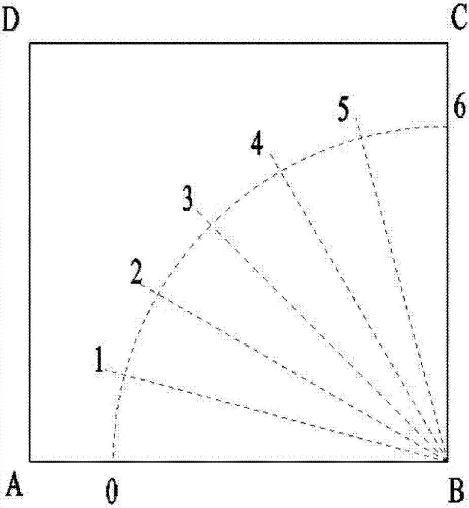
[0045] combine figure 2 and practical examples to further illustrate the invention:

[0046] This example demonstrates the application of the present invention through arc cutting on common white glass. The size of the liquid crystal glass is 100mm×100mm×1.1mm, and now an arc with a radius of 80mm is cut out on it, such as figure 2 shown. The calculated sampling points 1, 2, 3, 4, and 5 are evenly distributed along the arc with an interval of 15°. The fracture toughness K of this liquid crystal glass is determined by experiments. IC At 0.7MPa·(mm) 1 / 2 to 0.8MPa·(mm) 1 / 2 between.

[0047] According to the maximum circumferential stress theory of brittle materials, curved cutting belongs to I and II composite fracture modes, and its fracture criterion and cracking angle θ prediction formula are as follows:

[0048] cos θ 2 [ K I cos 2 ...


PUM

PropertyMeasurementUnit
fracture toughnessaaaaaaaaaa

Abstract

The invention relates to a curved path cutting method of a brittle base plate by laser cutting, which comprises the following steps of: manufacturing an initial crack on the base plate as a cutting path, and setting sampling points; respectively obtaining the cracking angles theta at all sampling points; obtaining the current sampling point, and calculating out the stress intensity factors KI andKII according to the cracking angle theta at the current sampling point and the fracture toughness KIC of the base plate; solving temperature field distribution according to the stress intensity factors KI and KII of the current sampling point; regulating the parameters of a hot source and a cold source according to the obtained temperature field distribution so that the temperature field generated at the current sampling point is consistent with the calculated temperature field; and judging whether the current sampling point is the last sampling point or not, if not, then acquiring the next sampling point as the current sampling point, and turning to the step 2. The invention has the advantages of capability of ensuring a crack to propagate along the preset cutting path and high cutting accuracy.

Description

technical field [0001] The invention belongs to the field of precision cutting processing of brittle material substrates. technical background [0002] Brittle materials, such as silicon wafers, quartz crystals, engineering ceramics, liquid crystal glass, etc., are widely used in modern industry and daily life. Due to manufacturing and process, components made of these materials often require secondary processing such as cutting. [0003] For brittle material substrates, the traditional cutting process is to use diamonds, diamond or hard metal wheels to score lines, and then break them mechanically. Cutting in this way will easily produce debris during the processing process, the cut section is rough, and there are fine cracks, which require post-processing procedures such as edging and cleaning. The mechanical force in the processing process will also cause internal damage to components, becoming Potential factors for component failure. [0004] In order to overcome the ...

Claims


Application Information

Patent Timeline
Patent Type & Authority Patents(China)
IPC IPC(8): B23K26/36B23K26/42B23K26/38B23K26/60
Inventor 周国斌柴国钟卢炎麟姚建华王晨
Owner 苏州金盛瓷业有限公司
Why Eureka
Try Eureka