Energy recovery braking system for automobile suspension

A braking system and automobile suspension technology, applied in the direction of suspension, brakes, elastic suspension, etc., can solve the problems of reducing energy utilization efficiency, increasing the cost of energy conversion devices, restricting system design and structural layout, and achieving attenuation Vibration energy, the effect of improving ride comfort

Inactive Publication Date: 2010-11-17
一汽解放青岛汽车有限公司
View PDF7 Cites 17 Cited by
  • Summary
  • Abstract
  • Description
  • Claims
  • Application Information

AI Technical Summary

Problems solved by technology

[0005]The current energy-feeding suspension is mainly used in cars. Due to the limited installation space of the suspension, the energy-feeding system must have a compact structure, which undoubtedly restricts the design and structure of the system Arrangement; Most energy-feeding suspension structures and control algorithm design are rigid in using the vibration energy to control the suspension vibration, that is, only focus on the suspension system itself or the power system, and fail to extend to the entire vehicle, which is not in line with the integration , Systematic automobile design trend; some designs are dedicated to converting the suspension vibration kinetic energy into electric energy, storing it in the battery or directly driving it, which increases the cost of the energy conversion device and reduces the energy utilization efficiency

Method used


Image

  • Energy recovery braking system for automobile suspension
  • Energy recovery braking system for automobile suspension

Examples


Embodiment

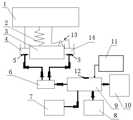
[0023] refer to figure 1 , the automobile suspension energy-feeding braking system of the present embodiment is arranged between the automobile suspension and the pneumatic braking system, and it includes an accumulator 6, an energy-feeding cylinder 4, an energy-feeding cylinder Ⅱ 14 、 The energy feed control module 11, one end of the energy feed cylinder 4 is connected to the suspension 1, the other end is connected to the accumulator 6, and the other end of the accumulator 6 is connected to the air storage tank 9 of the air pressure braking system. The cylinder body of the energy feeding cylinder 4 is fixedly arranged on the axle 3 , the piston rod end is arranged on the automobile suspension 1 , and a check valve 5 is arranged between the energy feeding cylinder 4 and the accumulator 6 . The energy feeding control module 11 is connected with the air storage tank 9 . The feed cylinder Ⅱ The cylinder body of 14 is fixedly arranged on the axle 3, and the piston rod end is c...


PUM


Abstract

The invention discloses an energy recovery braking system for an automobile suspension, which is arranged between the automobile suspension and a pneumatic braking system. The invention adopts the following technical scheme that the system comprises an energy accumulator, an energy recovery cylinder, an energy recovery cylinder II and an energy recovery control module, wherein one end of the energy recovery cylinder is connected with the suspension, the other end of the energy recovery cylinder is connected with the energy accumulator, and the other end of the energy accumulator is connected with an air reservoir of the pneumatic braking system; the cylinder body of the energy recovery cylinder is fixedly arranged on an axle, a piston rod end is arranged on the automobile suspension, and a non-return valve is arranged between the energy recovery cylinder and the energy accumulator; the energy recovery control module is connected with the air reservoir; and the cylinder body of the energy recovery cylinder II is fixedly arranged on the axle, the piston rod end is connected with the automobile suspension through a stroke lever, and a non-return valve is arranged between the energy recovery cylinder II and the energy accumulator. The new design is not only an energy saving design of energy feedback but also provides a certain damping characteristic for the original leaf spring suspension system, thereby being favorable for attenuating the vibration energy and improving the running smoothness of automobiles.

Description

[0001] technical field [0002] The invention belongs to an automobile suspension feed energy utilization device, in particular to an automobile suspension feed energy braking system. [0003] Background technique [0004] Energy saving technology is one of the top issues in current car design. In addition to new energy applications represented by electric vehicles, improved material structure, power storage technology, and drive strategies, opening up new energy regeneration or feedback channels is an effective means that the current automotive industry technology capabilities can achieve, such as relatively mature braking systems. Energy recovery technology has been successfully applied to F1 racing cars and BMW X6xDrive50i and other models. However, the vibration energy caused by the excitation of the uneven road surface during vehicle driving is not utilized, and is usually converted into heat energy by the vehicle suspension shock absorber and dissipated. Therefo...

Claims


Application Information

Patent Timeline
Patent Type & Authority Applications(China)
IPC IPC(8): B60T13/40B60G15/06
Inventor 李胜柳江孙启春高乃修胡金蕊周强
Owner 一汽解放青岛汽车有限公司
Why Eureka
Try Eureka