Portable static sediment sampler
A kind of sediment and portable technology, applied in the direction of sampling device, etc., can solve the problems of cumbersome operation, cumbersome, inability to obtain undisturbed, etc., and achieve the effect of simple operation, preventing interference and pollution, and enhancing the scientific nature of samples
- Summary
- Abstract
- Description
- Claims
- Application Information
AI Technical Summary
Problems solved by technology
Method used
Image
Examples
Embodiment 1
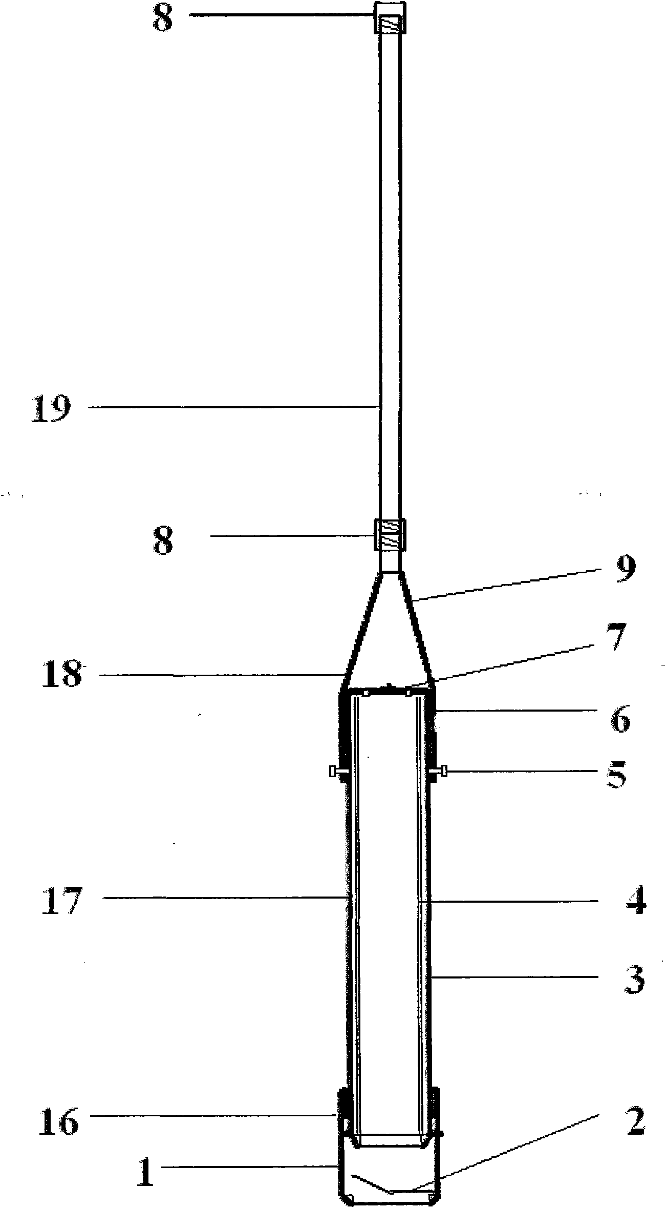
[0027] Example 1 combined figure 1 Explain the general structure of the present invention
[0028] figure 1 Among them, 16-19 represent four parts of the structure of the present invention respectively, that is, 16 is a fluid sediment collection chamber, 17 is a solid sediment collection chamber, 18 is a drainage chamber, and 19 is a connecting rod. The components of the present invention are respectively: 1 is the fluid sediment cavity, 2 is the one-way loose leaf, 3 is the solid sediment cavity, 4 is the cavity core, 5 is the connecting bolt, 6 is the lower edge of the drainage cavity, and 7 is the drainage Cavity bottom surface, 8 is short wire, and 9 is connecting rod. The fluid sediment collection chamber 16 is screwed to the solid deposit collection chamber 17 above it through threads; the solid deposit collection chamber 17 is connected to the drain chamber 18 above it through the connecting bolt 5; the drain chamber 18 is connected to the top by the short wire 8 Rod...
Embodiment 2
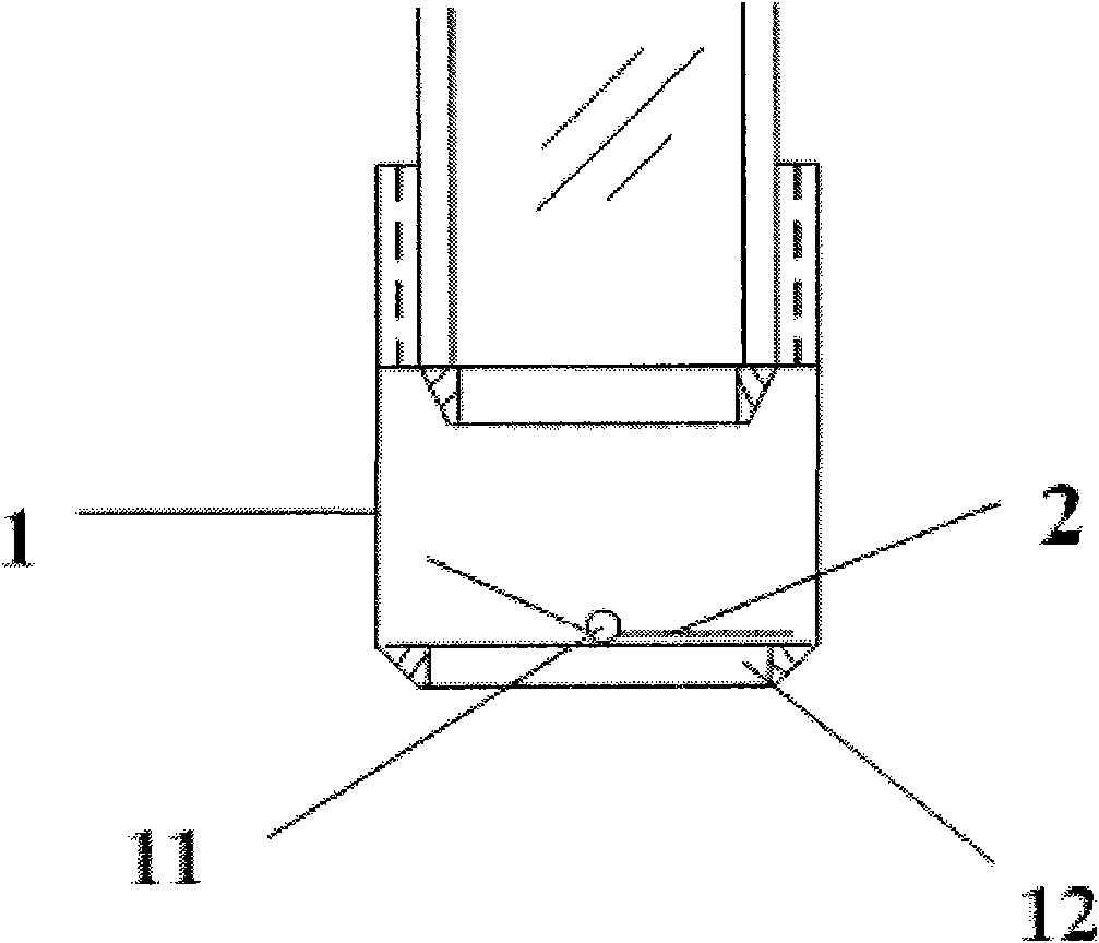
[0034] Example 2 combined figure 2 Illustrate the structure of fluid sediment collection chamber 16 among the present invention
[0035] figure 2 Among them, 1 is a fluid sediment cavity, 2 is a one-way movable leaf, which is two semicircular pieces, 11 is a central axis, and 12 is a casing. figure 2The vertical dotted line in represents that the liquid deposit collection chamber 16 and the solid deposit collection chamber 17 are screwed.
[0036] The casing 12 is fixedly installed inside the lower end of the fluid deposit cavity 1 , or is integrally made with the fluid deposit cavity 1 inside the lower end of the fluid deposit cavity 1 .
[0037] The straight sides of the two one-way flaps 2 are dynamically connected to the central axis 11, and the two one-way flaps 2 can rotate around the central axis 11; the fall of the two one-way flaps 2 will be blocked by the sleeve 12, and they are in a flat state It forms a circle, which can cover and seal the fluid sediment cham...
Embodiment 3
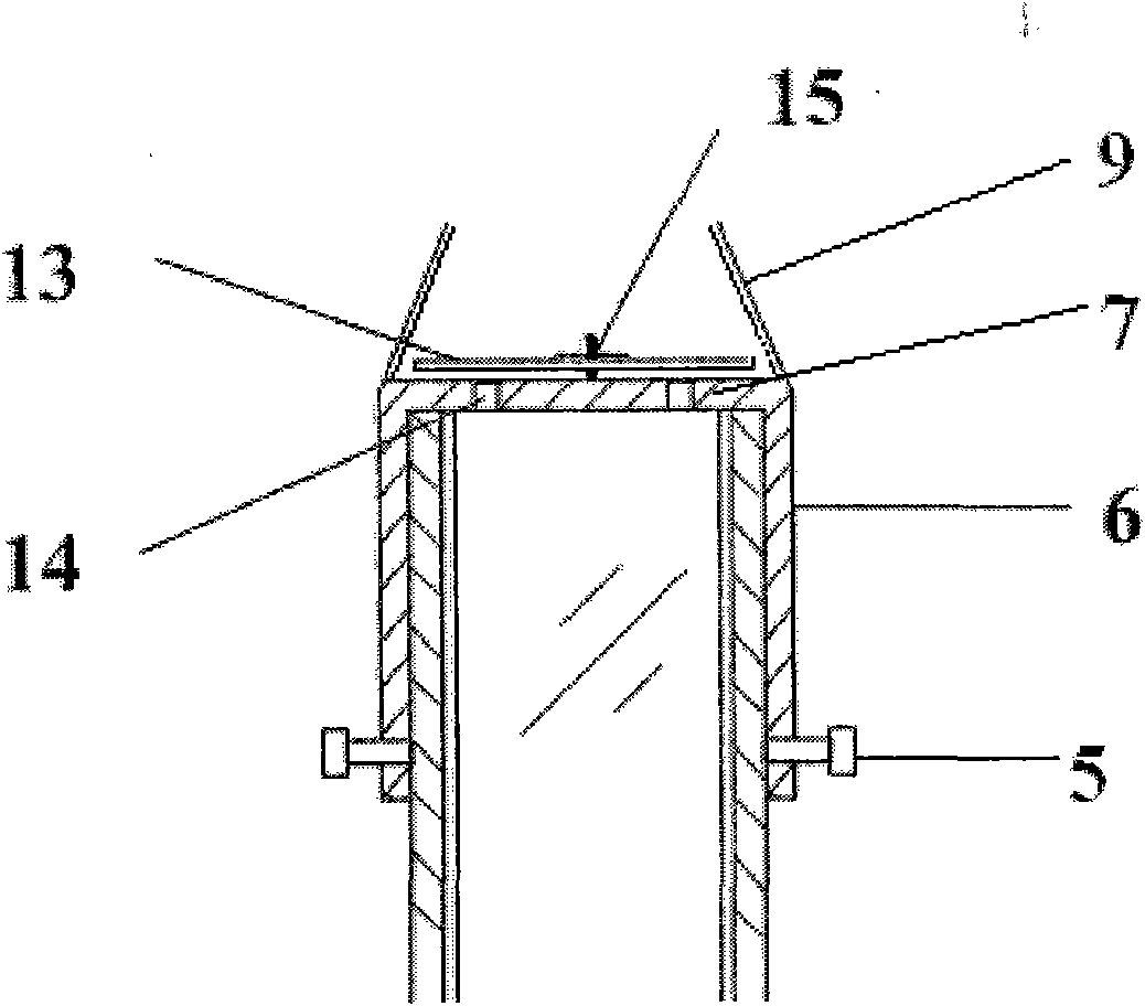
[0039] Example 3 combined image 3 Describe the structure of the drainage cavity 18 in the present invention
[0040] image 3 Among them, 6 is the lower edge of the drainage chamber, 7 is the bottom surface of the drainage chamber, 13 is a rubber flap, which can be a circular rubber cover with the same radius as the inner radius of the drainage chamber, and 14 is a drainage hole, which is vertically opened on the bottom surface 7 of the drainage chamber , 15 is a fixing bolt, and the center of the rubber flap 13 is fixed at the center of the bottom surface 7 of the drain cavity.
[0041] During the draining process, the rubber flap 13 on the top is opened around, and water flows out through the drain hole 14 . When the sediment collection is completed and the static sediment sampler is lifted upwards, the upper hydraulic pressure makes the rubber flap 13 fall back to seal the drainage hole 14, so that a negative pressure is formed inside the static sediment sampler, and the...
PUM
 Abstract
Description
Claims
Application Information
 - R&D
- Intellectual Property
- Life Sciences
- Materials
- Tech Scout
- Unparalleled Data Quality
- Higher Quality Content
- 60% Fewer Hallucinations
Browse by: Latest US Patents, China's latest patents, Technical Efficacy Thesaurus, Application Domain, Technology Topic, Popular Technical Reports.
© 2025 PatSnap. All rights reserved.Legal|Privacy policy|Modern Slavery Act Transparency Statement|Sitemap|About US| Contact US: help@patsnap.com


