
Circuit of aging test stand for engine electronic control units

An electronic control unit and aging test technology, which is applied in general control systems, control/adjustment systems, test/monitoring control systems, etc., can solve the problems of inability to simulate the working status of the electronic control unit ECU, multiple functions of components, waste, etc.

Inactive Publication Date: 2012-03-07
WUXI LONGSHENG TECH
View PDF0 Cites 0 Cited by
  • Summary
  • Abstract
  • Description
  • Claims
  • Application Information

AI Technical Summary

Problems solved by technology

[0003] At present, in the aging test device of the electronic control unit ECU, the components selected have many functions but are single-purpose, resulting in a lot of waste, and can only make a small number of products at a time, which has brought a lot of trouble to mass production. The challenge is that the working status of the electronic control unit ECU on the vehicle cannot be simulated. The speed signal is a purchased signal generator, and two regulated power supplies are used. The sensor signals are also actually measured by the sensor, which is expensive and placed confusion

Method used


Image

  • Circuit of aging test stand for engine electronic control units
  • Circuit of aging test stand for engine electronic control units

Examples


Embodiment Construction

[0014] The invention will be further described below in conjunction with the accompanying drawings.

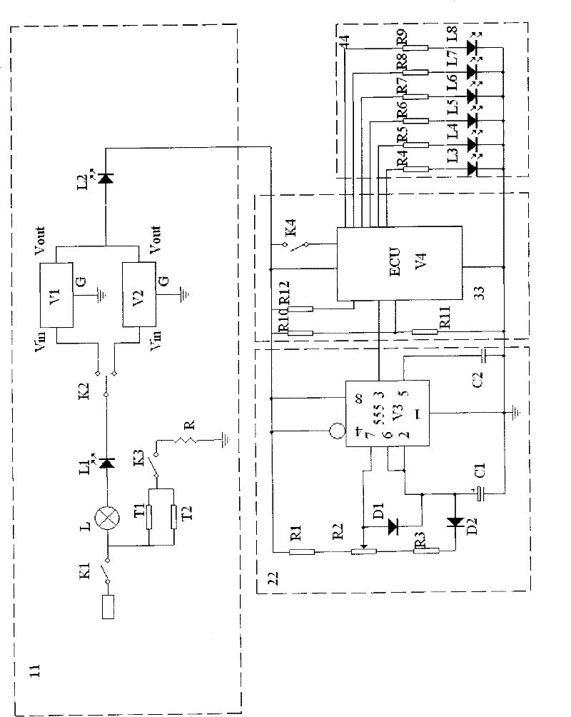
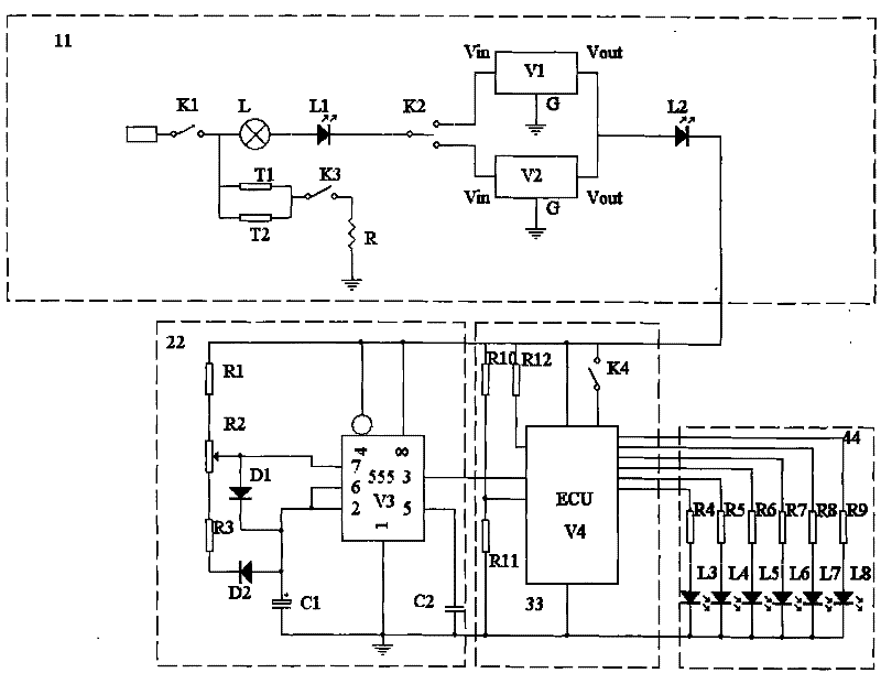
[0015] An aging test bench circuit for an engine electronic control unit is formed by connecting four parts: a power supply part 11 , a rotational speed signal circuit 22 , an analog sensor signal circuit 33 , and a signal output circuit 44 .

[0016] The power supply part 11 includes: a first power switch K1, a power indicator light L connected in series after the first power switch K1, a first light-emitting diode L1, a 12V and 24V switching dial switch K2, a 12V and 24V switching dial switch The 12V regulated switching power supply V1 and the 24V regulated switching power supply V2 are connected in parallel after K2, and the second light-emitting diode L2 is connected in series after the two regulated switching power supplies. A second power switch K3 and a group of heating wires R are sequentially connected in series behind the timer T2, the temperature setting device T1 a...


PUM


Abstract

The invention discloses a circuit of an aging test stand for engine electronic control units (ECUs), which consists of a power supply part, a rotating speed signal circuit, an analog sensor signal circuit and a signal output circuit which are connected. The power supply part comprises a first power switch, a power indicator, a first light-emitting diode and a 12V and 24V changeover toggle switch which are sequentially connected in series behind the first power switch, a 12V voltage-stabilizing switch power supply and a 24V voltage-stabilizing switch power supply which are connected in parallel behind the 12V and 24V changeover toggle switch, and a second light-emitting diode which is connected in series behind the two voltage-stabilizing switch power supplies, wherein a temperature setterand an electronic timer are synchronously connected in parallel behind the first power switch; and a second power switch and a group of heating wires are sequentially connected in series behind the temperature setter and the electronic timer. After the power switches and a trigger switch are turned on, six light-emitting diodes for EGR valve output, high idle speed output, return oil output, pre-heating indicator, pre-heating plug output and timing output are lightened according to different programs; the ECUs can be judged according to the brightness of the diodes, and the aim of the aging test is fulfilled.

Description

technical field [0001] The invention relates to an aging test bench circuit of an engine electric control unit, which belongs to the field of electrical control systems. Background technique [0002] The engine electronic control unit ECU is the control core of the EGR system of the engine exhaust gas recirculation system. The main functions of the ECU currently produced are EGR control and oil pump timing control system. At the same time, it also has preheating, oil return control, high idle speed, and fault diagnosis. and other functions. [0003] At present, in the aging test device of the electronic control unit ECU, the components selected have many functions but are single-purpose, resulting in a lot of waste, and can only make a small number of products at a time, which has brought a lot of trouble to mass production. The challenge is that the working status of the electronic control unit ECU on the vehicle cannot be simulated. The speed signal is a purchased signal ...

Claims


Application Information

Patent Timeline
Patent Type & Authority Patents(China)
IPC IPC(8): G05B23/00
Inventor 邵兴隆倪铭肖琳都兴鹏徐行
Owner WUXI LONGSHENG TECH
Learn More