High dynamic range video imaging system and image generating method

A technology of high dynamic range and imaging system, which is applied in parts of TV system, image enhancement, image communication, etc. It can solve problems such as unhandling, blurring, difficult high-speed and effective processing, etc., and achieve good market promotion prospects and rich visual information , Guarantee the effect of synchronization and real-time

Active Publication Date: 2010-11-17
SHENZHEN INST OF ADVANCED TECH CHINESE ACAD OF SCI
View PDF5 Cites 54 Cited by
  • Summary
  • Abstract
  • Description
  • Claims
  • Application Information

AI Technical Summary

Problems solved by technology

[0004] The traditional scheme of single dynamic range enhanced image generated based on images with different exposure times can only shoot for a single static scene, and has high requirements on the lighting and environment of the scene. This type of equipment cannot perform dynamic real-time shooting of continuous scenes.
[0005] The traditional high-dynamic video method based on single-frame image processing uses image processing methods to analyze the brightness and color of independent frames of the video, thereby improving its contrast, brightness, saturation and other observation indicators. Although the visual effect has improved, but It cannot handle information loss caused by highlights, overexposure, shadows, etc. in the previous shooting
[0006] Traditional high dynamic range video shooting based on different exposure time is similar to the principle described in the scheme of single dynamic range enhanced image generated based on different exposure time images, but for high dynamic range video image shooting of dynamic scenes, its main The problem is that due to the time difference caused by the use of multiple exposure times, it causes smearing and blurring, and it is easy to cause serious problems such as loss of shooting targets for high-speed motion and changing scenes. The method is still difficult to achieve high-speed and effective processing

Method used


Image

  • High dynamic range video imaging system and image generating method
  • High dynamic range video imaging system and image generating method
  • High dynamic range video imaging system and image generating method

Examples


Embodiment Construction

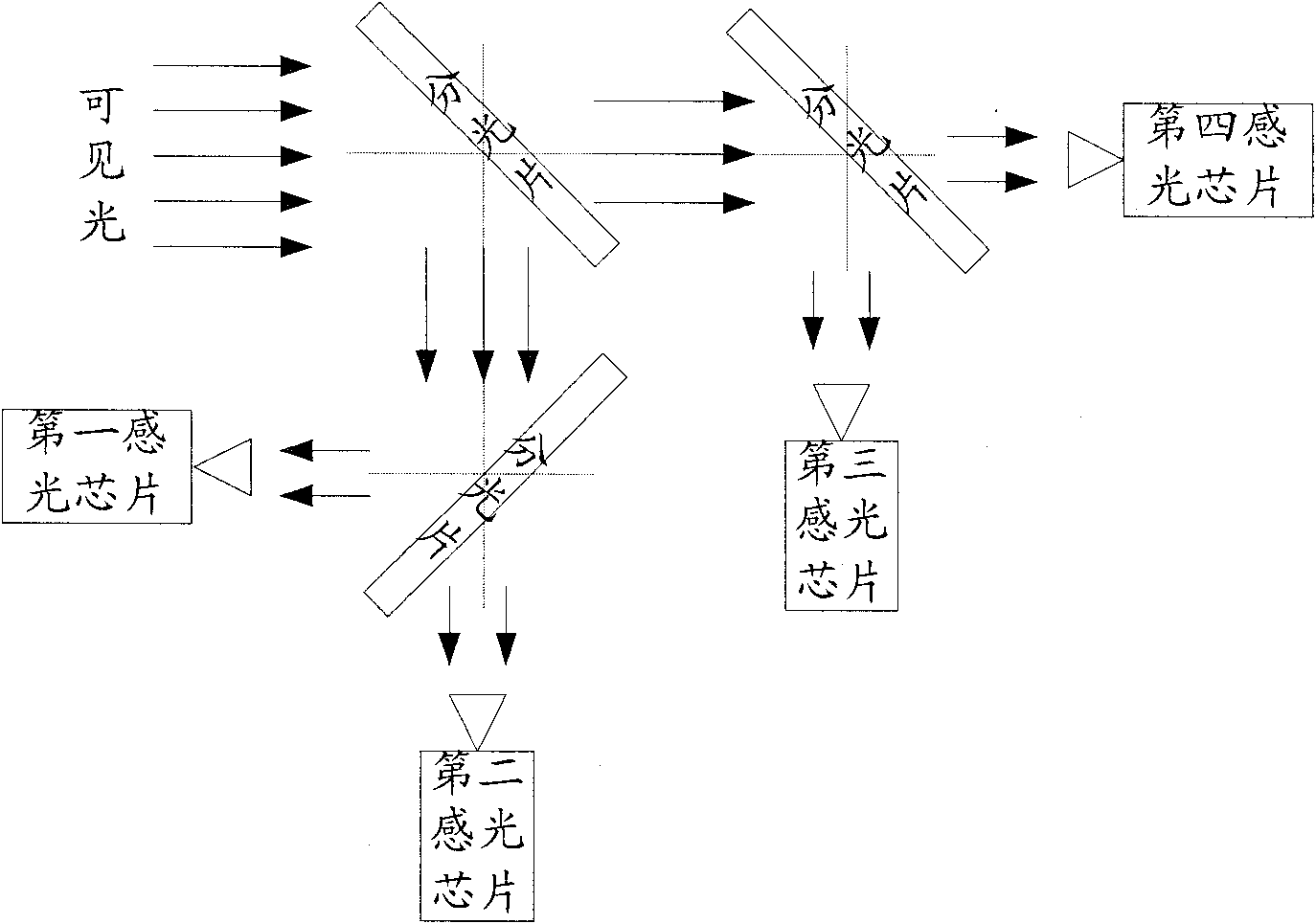
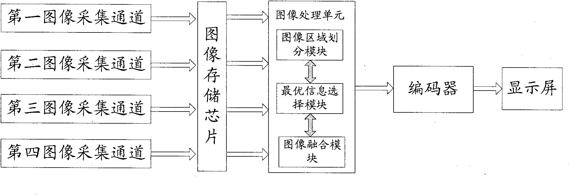
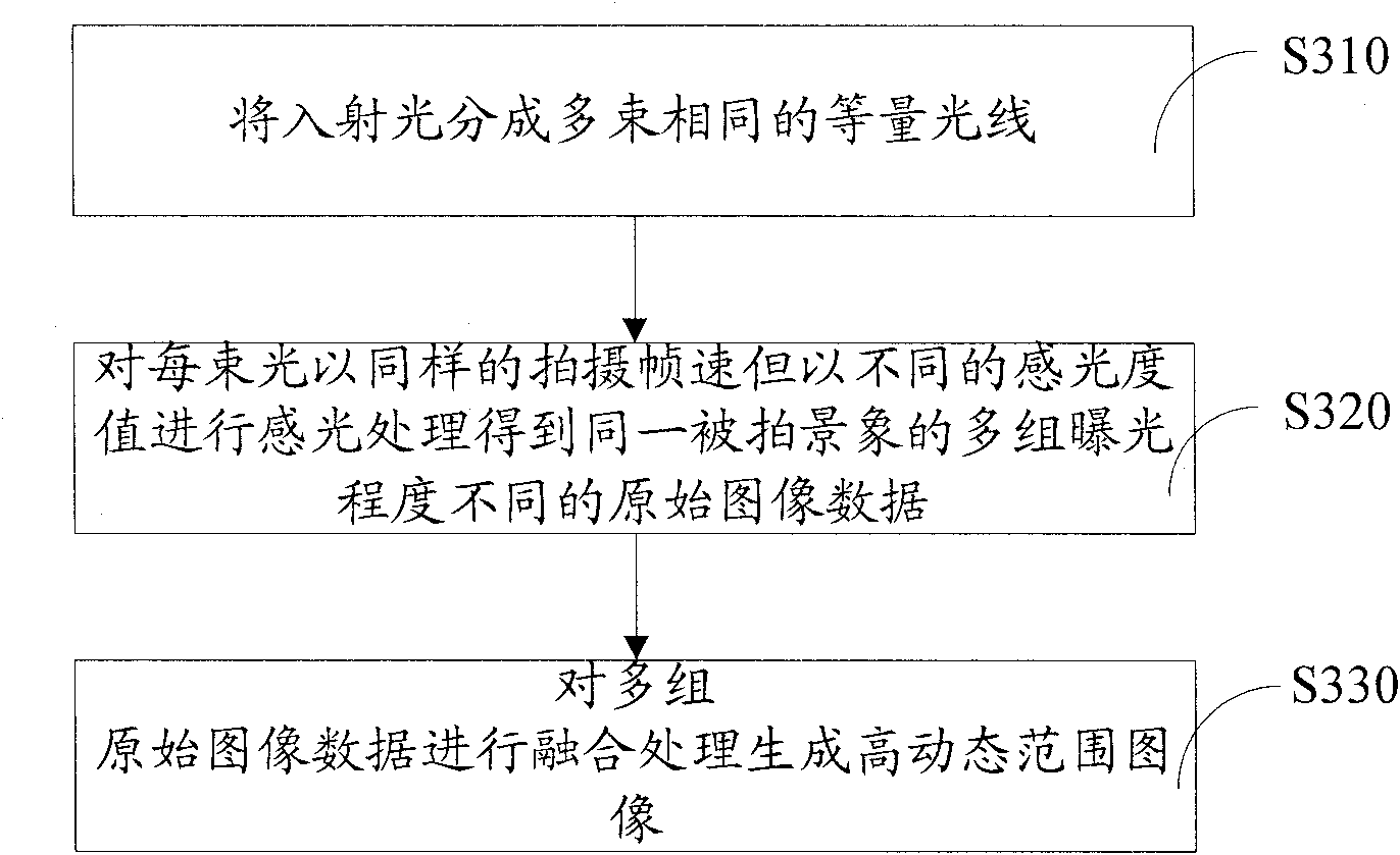
[0029] By setting a beam splitter, the external radiation entering the optical lens is divided into multiple beams of equal amount, and the multiple photosensitive chips are set to different sensitivity values, so as to simultaneously generate multiple original images with different exposures for the same scene. Image, and then realize real-time video frame image fusion processing through dynamic multi-sensitivity image fusion method, so that the final generated video image has higher dynamic range characteristics.

[0030] The following mainly describes the high dynamic range video imaging system and its image generation method integrated by multiple photosensitive chips with the accompanying drawings.

[0031] The high dynamic range video imaging system includes optical lens, beam splitter, photosensitive chip, image processing unit and peripheral system.

[0032] The spectroscope can use ordinary spectroscopy, and its spectroscopy wavelength range is within the visible light wavel...


PUM


Abstract

The invention relates to a high dynamic range video imaging system and an image generating method. The system comprises an optical lens, an image processing unit, at least an optical splitter and a plurality of sensitive chips. The optical splitter splits the incident light penetrating through the optical lens into a plurality of beams which enter the plurality of sensitive chips so as to obtain image data with different exposures. The image processing unit fuses the image data to generate high dynamic range images. Each sensitive chip used by the high dynamic range video imaging system fused by the plurality of sensitive chips has same specifications so that synchronization and instantaneity of photographing can be ensured. Meanwhile, the generated video image has obvious advantage in color and luminance uniformities and affluent visual information compared with single exposed image, can effectively solve the problems of underexposure, overexposure and color and luminance non-uniformities in traditional image pickup systems and has great market applicable foreground.

Description

【Technical Field】 [0001] The invention relates to the field of computer vision and image processing, in particular to a high dynamic range video imaging system and an image generation method. 【Background technique】 [0002] The traditional high dynamic image generation method usually uses the same photosensitive chip to obtain different exposure photos by setting different exposure times, and then merge to generate images with high dynamic range. Its essence determines that it can only be used for still photography, but cannot be processed. Dynamic scenes and objects. [0003] With the development of image sensing technology, video shooting has also entered the high-definition era, but only the increase in the resolution of video capture equipment has been difficult to meet people's viewing needs. In the field of image and video processing, more attention is paid to how to obtain the high dynamic range and color fidelity similar to that of the human visual system. However, due to ...

Claims


Application Information

Patent Timeline
Patent Type & Authority Applications(China)
IPC IPC(8): H04N5/235H04N5/232G02B27/10G06T5/50
Inventor 宋展吴晓军
Owner SHENZHEN INST OF ADVANCED TECH CHINESE ACAD OF SCI
Why Eureka
Try Eureka