
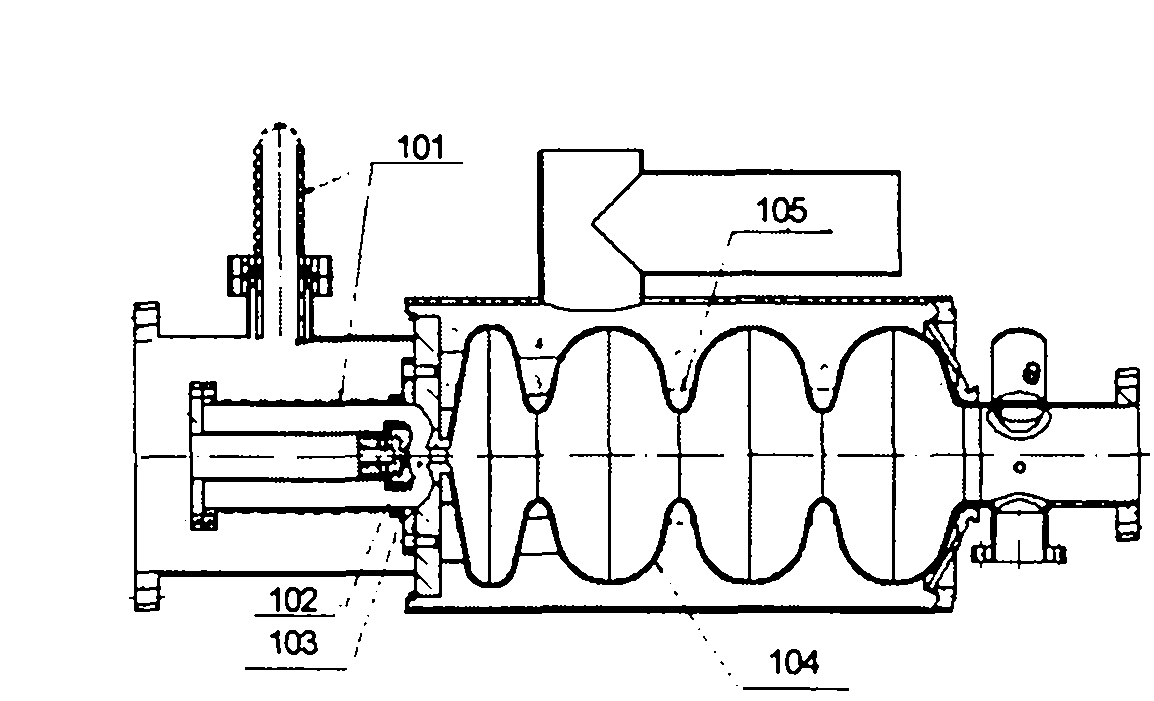
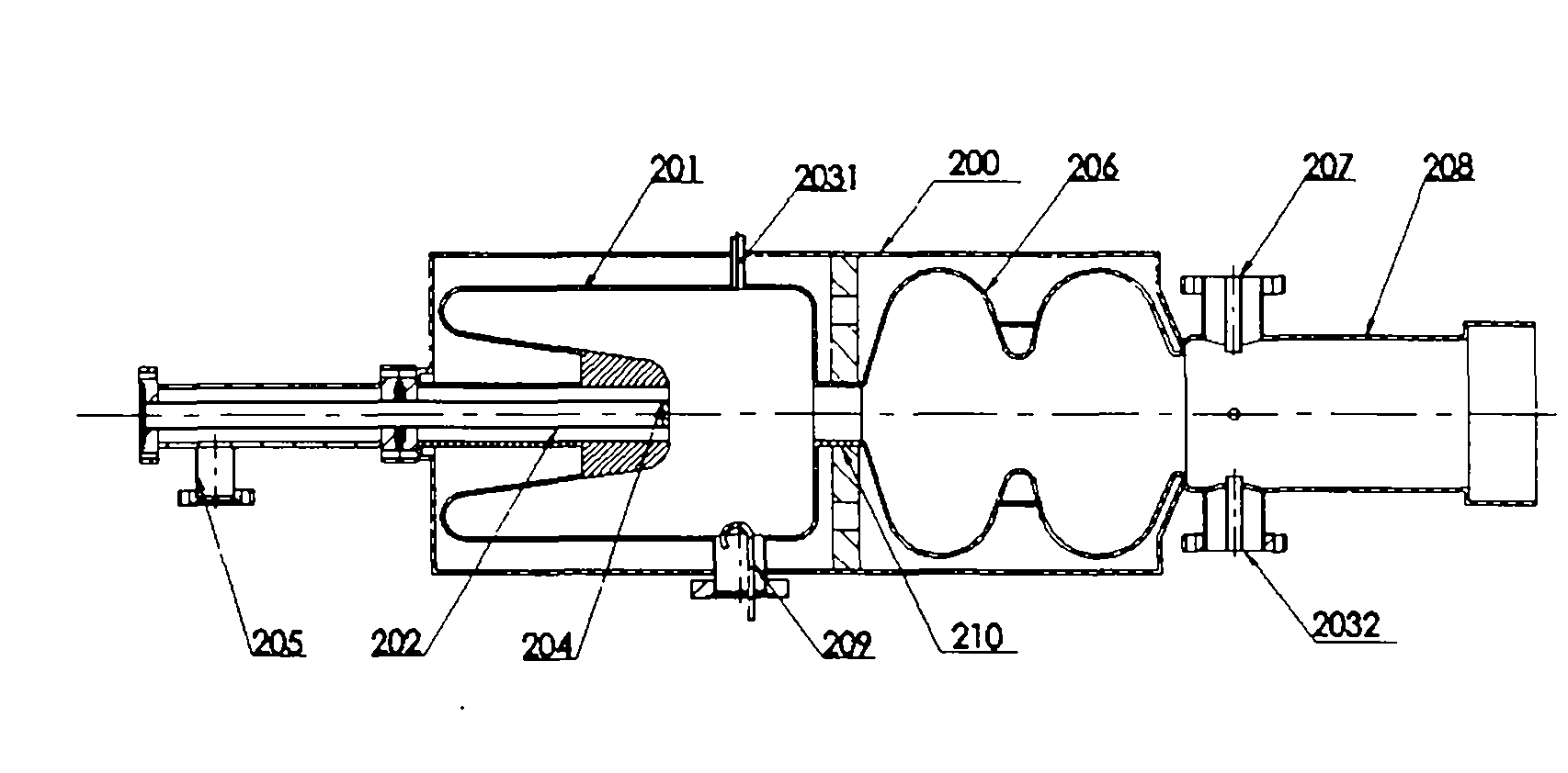
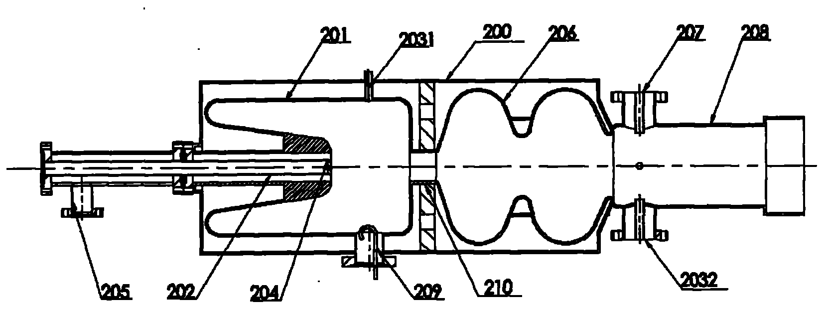
Major structure of dual-mode superconductive photocathode injector

A main structure, photocathode technology, applied in the direction of DC voltage accelerators, electrical components, accelerators, etc., can solve the problems of falling investment costs, low average power of XFEL, and difficulty in completing experiments successfully, and achieve low emissivity and high average current. strong effect

Inactive Publication Date: 2010-11-17
赵夔
View PDF4 Cites 13 Cited by
  • Summary
  • Abstract
  • Description
  • Claims
  • Application Information

AI Technical Summary

Problems solved by technology

The investment of the fourth-generation light source (X-ray free electron laser, XFEL for short) is billions of RMB. If the emittance can be reduced by an order of magnitude, the overall investment cost will be doubled.
this low repetition rate greatly limits the number of subscriber stations an XFEL device can provide
Not only that, due to the low repetition frequency of electron beams provided by the accelerator, the average power of the XFEL produced by it is very low, which makes it take longer for users to collect data, thus greatly prolonging the period of their research work, and even causing their The experiment is difficult to complete successfully

Method used


Image

  • Major structure of dual-mode superconductive photocathode injector
  • Major structure of dual-mode superconductive photocathode injector
  • Major structure of dual-mode superconductive photocathode injector

Examples


Embodiment Construction

[0017] The dual-mode superconducting photocathode injector proposed by the present invention is described in detail in conjunction with the accompanying drawings and embodiments as follows:

[0018] The core component of the present invention is a dual-mode dual-frequency superconducting cavity (where β To characterize the speed of accelerated particles, low β generally means that the particle speed is much lower or lower than the speed of light, and high β means that the particle speed is close to the speed of light. Hereinafter referred to as the dual-mode superconducting cavity), the QWR cavity and the high β ellipsoidal cavity pass through a beam tube connected; the QWR cavity is a low-energy electron beam extraction cavity, and the high-β cavity is a beam-enhancing cavity for electron beams. The frequencies of the two cavities are frequency-doubling and synchronous.

[0019] The main structure of the dual-mode superconducting photocathode injector of the present invention...


PUM


Abstract

The invention relates to a major structure of a dual-mode superconductive photocathode injector, belonging to the technical field of accelerators. In the major structure, the QWR superconductor cavity of a low-frequency TEM mode and the high beta ellipsoidal superconductor cavity of a high frequency TM mode forms a dual-mode dual-frequency superconductor cavity, the QWR superconductor cavity and the high beta ellipsoidal superconductor cavity are connected through a beam tube, the QWR superconductor cavity is used for leading out a low-energy electron beam, the high beta ellipsoidal superconductor cavity is used for bunching and energizing the electron beam, and the frequencies of the two cavities are in frequency multiplication and synchronization relation. The electron beam produced by the invention has the advantages of ultra-short pulse, ultra-low emittance and high average current.

Description

technical field [0001] The invention belongs to the technical field of accelerators, in particular to a main structure design of an electron gun using radio frequency superconducting technology. Background technique [0002] The electron gun that provides electron beams for electron accelerators is an important key technology in the field of accelerators. As a result of years of research and development, there are two main types of electron guns for electron accelerators, namely DC electron guns and radio frequency electron guns. Since the 1980s, due to the advanced scientific devices such as free electron laser devices, high-current linear electron accelerators, and ERL light sources in the high-tech field, high requirements have been placed on the quality of electron beams, and traditional hot-cathode electron guns cannot meet the requirements. , resulting in a laser-driven photocathode DC electron gun and a laser-driven photocathode RF electron gun. These two electron g...

Claims


Application Information

Patent Timeline
Patent Type & Authority Applications(China)
IPC IPC(8): H05H5/02
Inventor 赵夔朱凤郝建奎焦飞
Owner 赵夔
Learn More