Transformer structure

A technology of transformers and magnetic cores, applied in the field of transformers, can solve problems such as large overall volume, and achieve the effects of reducing overall volume, saving manufacturing time, and reducing temperature

Inactive Publication Date: 2010-11-24
DELTA ELECTRONICS INC
View PDF0 Cites 2 Cited by
  • Summary
  • Abstract
  • Description
  • Claims
  • Application Information

AI Technical Summary

Problems solved by technology

[0009] The main purpose of the present invention is to provide a transformer structure to solve the defect that the existing transformer tends to make the overall volume larger when increasing the air gap distance between the two middle columns of the magnetic core group to adjust the inductance of the transformer

Method used


Image

  • Transformer structure
  • Transformer structure
  • Transformer structure

Examples


Embodiment Construction

[0041] Some typical embodiments embodying the features and advantages of the present invention will be described in detail in the following description. It should be understood that the present invention can have various changes in different forms without departing from the protection scope of the present invention, and the description and drawings therein are used as illustrations in essence, not to limit the present invention .

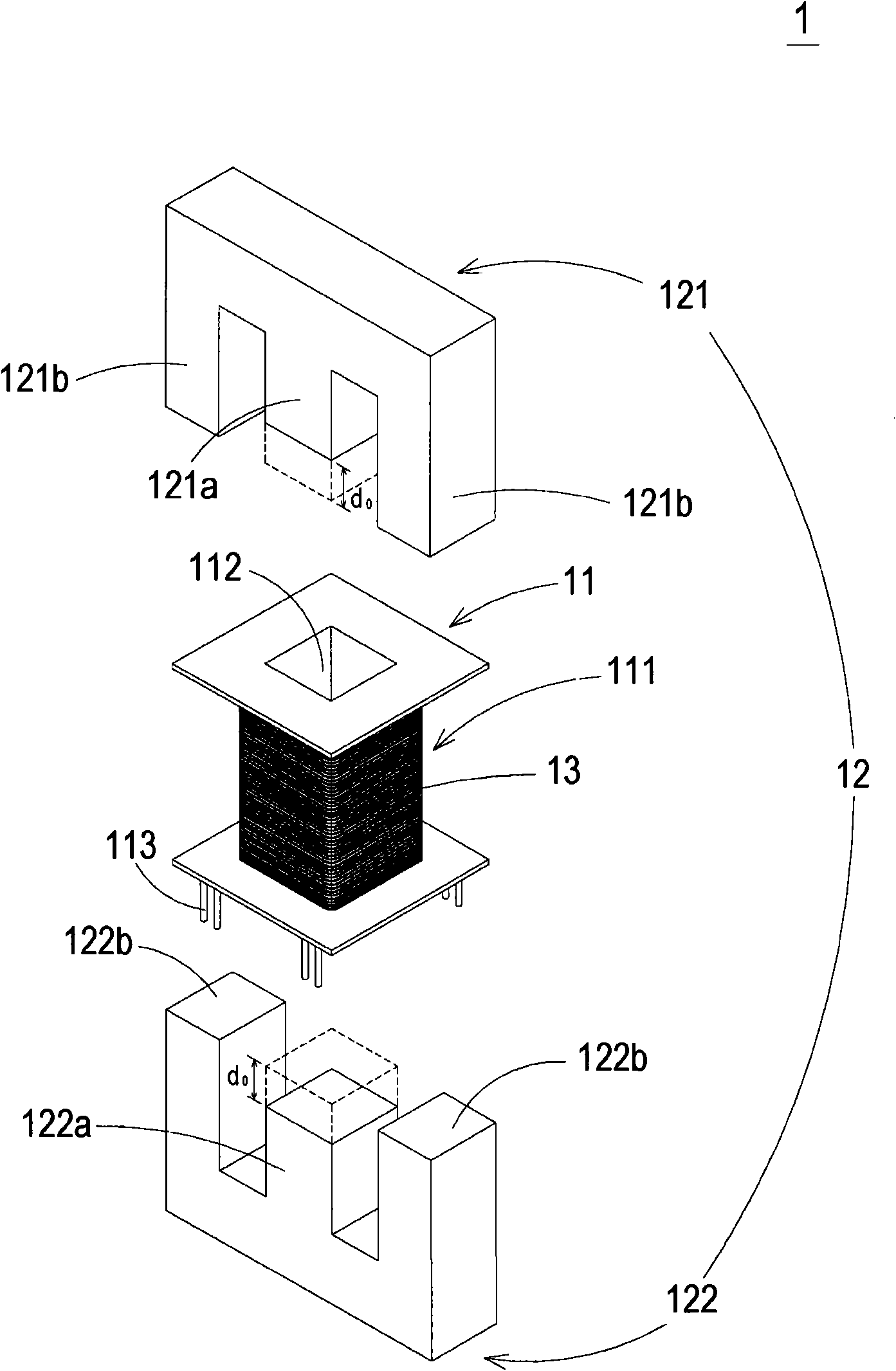
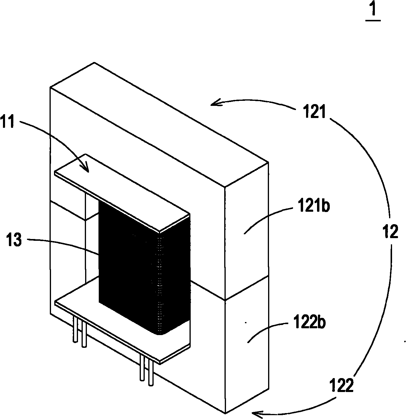
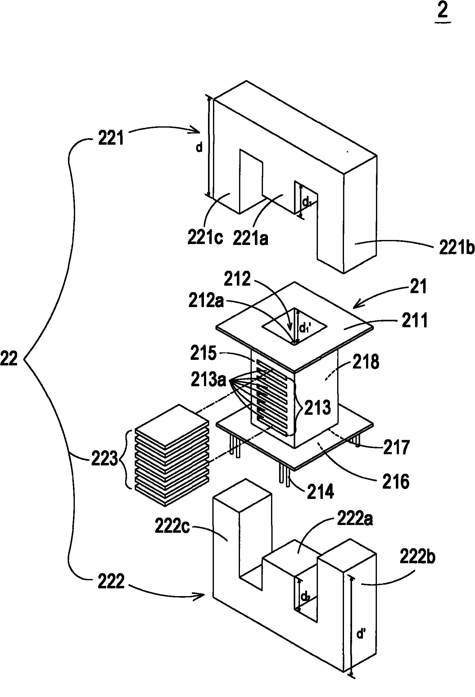
[0042] see Figure 2A and Figure 2B , which are respectively a schematic diagram of an exploded structure and a schematic diagram of an assembled structure of the transformer structure of the first preferred embodiment of the present invention. As shown in the figure, the transformer 2 of the present invention mainly includes a base 21, a magnetic core group 22 and at least one winding 23 (such as Figure 2C shown), wherein the base 21 has a first accommodating space 212 and a plurality of first accommodating grooves 213, and the magnetic core gro...


PUM


Abstract

The invention relates to a transformer structure which at least comprises a base, a magnetic core group, a second magnetic core element and at least a winding. The base is provided with an accommodation room and at least an accommodation groove. The magnetic core group comprises a first magnetic core element, a second magnetic core element and a third magnetic core element, wherein the first magnetic core element is provided with a first column, and the third magnetic core element is arranged in the first accommodation groove selectively. The winding is arranged on the base. The base is arranged between the first and second magnetic core elements, and the first column is arranged in the first accommodation room. The third magnetic core element is arranged selectively in the first accommodation groove to adjust the air gap distance between the third magnetic core element and the first magnetic core element and between the third magnetic core element and the second magnetic core element. In the invention, the temperature of the transformer can be reduced so that the transformer fully meets the safety requirements and maintains the inductance needed for operation. The whole process of the transformer can be simplified by the elements including the normalized magnetic core group, the base and the like so that the manufacturing time and cost of the transformer are saved effectively, the whole volume is reduced, and the assembly is easy.

Description

technical field [0001] The invention relates to a transformer, in particular to a transformer structure with distributed air gaps. Background technique [0002] Generally speaking, there are often many magnetic components in electrical equipment, such as transformers, inductance components, etc., and in order to correspond to the thinning of electrical equipment, the magnetic components and the conductive windings used inside must also develop towards a thinner trend to reduce electrical appliances. The overall volume of the device. [0003] Taking the transformer as an example, the existing transformer structure is as follows: Figure 1A As shown, as shown in the figure, the transformer 1 is mainly composed of a winding frame 11, a magnetic core group 12 and a coil 13, wherein the winding frame 11 has a winding slot 111, and the winding slot is used for the coil 13 to be wound on On it, and in the bobbin 11 there is also a through channel 112 . The bottom of the bobbin 11...

Claims


Application Information

Patent Timeline
Patent Type & Authority Applications(China)
IPC IPC(8): H01F30/06H01F27/24
Inventor 刘家铭陈志明赖育骏
Owner DELTA ELECTRONICS INC
Why Eureka
Try Eureka