Burst luminous signal amplification method, burst luminous amplifer, system and communication system

A light-emitting signal and optical amplifier technology, applied in the field of communication, can solve problems such as sudden optical signal surge and signal distortion, and achieve the effects of avoiding surge phenomenon, reducing delay time, and avoiding hole burning

Inactive Publication Date: 2010-11-24
HUAWEI TECH CO LTD
View PDF3 Cites 15 Cited by
  • Summary
  • Abstract
  • Description
  • Claims
  • Application Information

AI Technical Summary

Problems solved by technology

The uplink signal is a burst optical signal. If an ordinary optical amplifier is used, for example, the current one based on automatic gain control (Automatic Gain Control, AGC), automatic current control (Automatic Current Control, ACC), automatic power control (Automatic Power Control, APC) and supplementary light technology optical amplifiers, because the typical transient effect response time constant of ordinary optical amplifiers is on the order of microseconds, burst optical signals will generate surges after being amplified by ordinary optical amplifiers, resulting in signal distortion
Moreover, in other optical transmission technologies other than PON, when burst light needs to be amplified, the same problem also exists

Method used


Image

  • Burst luminous signal amplification method, burst luminous amplifer, system and communication system
  • Burst luminous signal amplification method, burst luminous amplifer, system and communication system
  • Burst luminous signal amplification method, burst luminous amplifer, system and communication system

Examples


Embodiment Construction

[0038] The technical solutions of the present invention will be described in further detail below with reference to the accompanying drawings and embodiments.

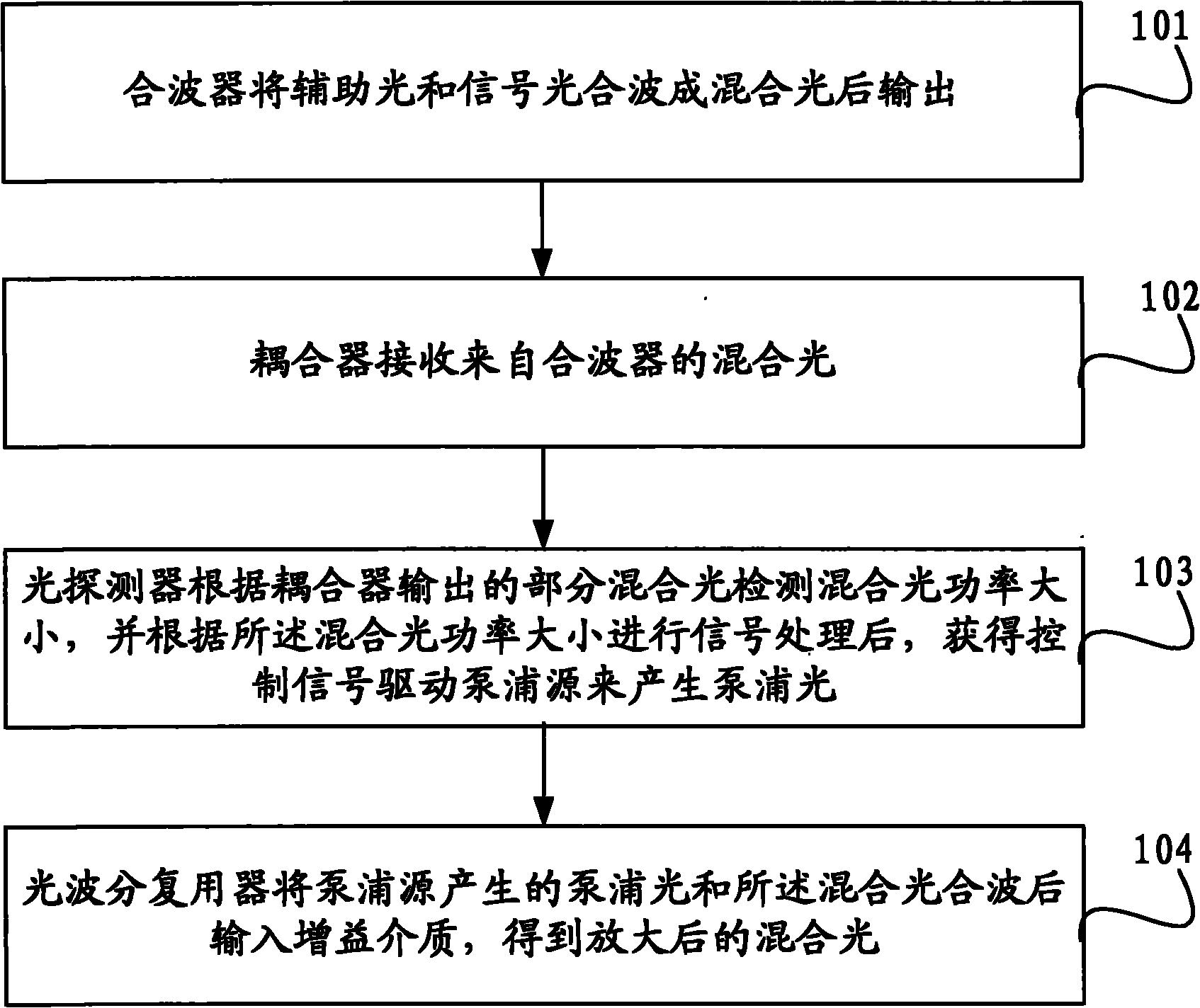
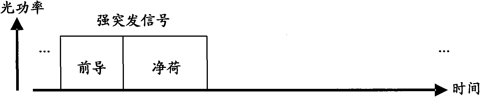
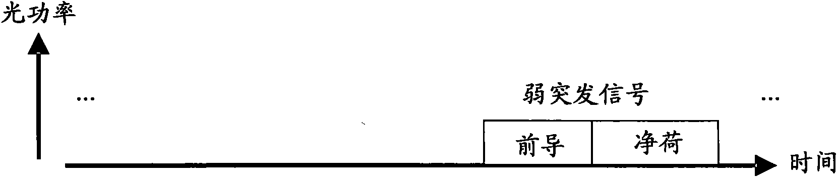
[0039] In the prior art, the response time constant of typical transient effects of ordinary doped optical amplifiers is relatively large, and when burst light is amplified by ordinary optical amplifiers, surges will occur or the optical amplifiers will turn on too slowly, resulting in distortion of transmission signals. The embodiment of the present invention proposes a method, by adding auxiliary light to the optical signal input by the optical amplifier, so that there is always non-burst light passing through the optical amplifier, avoiding the surge and also avoiding the slow startup phenomenon. Since the power setting of the auxiliary light is independent of the power of the signal light, it can be set very low, avoiding the effect of hole burning, and meeting the requirements of burst light amplification. Further...


PUM


Abstract

The embodiment of the invention relates to a burst luminous signal amplification method, a burst luminous amplifer, a system and a communication system. The burst luminous signal amplification method comprises the steps: combing fill-in lights and signal lights into a mixed light through a combiner and then outputting, wherein the fill-in lights are non-burst lights, the signal lights are burst lights, and the power sets of the fill-in lights is dependent of the watt level of the signal lights; generating pumping lights; and combing the pumping lights and the mixed light by a wave division multiplexer and then inputting a gain medium to obtain the amplified mixed light. In the burst luminous signal amplification method, the burst luminous amplifer, the system and the communication system, due to the occurrence of the fill-in lights, the burst luminous signal amplifer works in an amplification state all the time, the gain medium is provided with the pumping lights which can directly amplify the entered signal lights, thereby reducing the delay time of opening the burst luminous amplifer, improving the transient response speed of the burst luminous amplifer and avoiding generation of surging and signal distortion.

Description

technical field [0001] Embodiments of the present invention relate to communication technologies, and in particular to a burst optical signal amplification method, burst optical amplifier and system, and a communication system. Background technique [0002] With the rapid development of communication technologies, passive optical network (Passive Optical Network, PON) technology is currently one of the most widely used fiber-to-the-home technologies in access networks. The network architecture of PON of various systems is basically the same, including Optical Line Terminal (OLT), Optical Network Unit (Optical Network Unit, ONU) and Optical Distribution Network (ODN); among them, OLT is located in the center The ONU is located in the user's home, roadside or building, and the OLT and the ONU are connected by a passive ODN. The OLT and ODN are connected by a backbone optical fiber. The ODN implements point-to-multipoint optical power distribution and is connected to multiple ...

Claims


Application Information

Patent Timeline
Patent Type & Authority Applications(China)
IPC IPC(8): H04B10/17H04J14/02H04B10/12H04B10/296
CPCH04B10/296
Inventor 刘鸿丁锋
Owner HUAWEI TECH CO LTD
Why Eureka
Try Eureka