
Protection switching method and device in Ethernet passive optical network

A passive optical network and protection switching technology, which is applied in the direction of selection devices, data switching networks, multiplexing system selection devices, etc., can solve the serious data packet loss rate, the performance degradation of protection switching, and the difficulty of guaranteeing service recovery, etc. problem, to achieve the effect of short switching time and reduced impact

Inactive Publication Date: 2010-11-24
ZTE CORP
View PDF0 Cites 35 Cited by
  • Summary
  • Abstract
  • Description
  • Claims
  • Application Information

AI Technical Summary

Problems solved by technology

At present, the implementation methods of all-fiber protection are relatively complicated, and this increase in complexity also brings about a decrease in protection switching performance.
[0004] Generally speaking, the commonly used implementation methods will cause the ONU to re-register after the protection switching occurs, and this takes a long time in the service recovery stage after the switching, because this part has a discovery cycle of at least 50ms plus about With a window size of 200us (the worst case for a single ONU), plus the time for upper-layer protocol processing and registration, it is difficult to guarantee service recovery within 50ms after switching, which will result in failure to meet the requirements of carrier-grade equipment. The data packet loss rate will be more serious

Method used


Image

  • Protection switching method and device in Ethernet passive optical network
  • Protection switching method and device in Ethernet passive optical network
  • Protection switching method and device in Ethernet passive optical network

Examples


Embodiment Construction

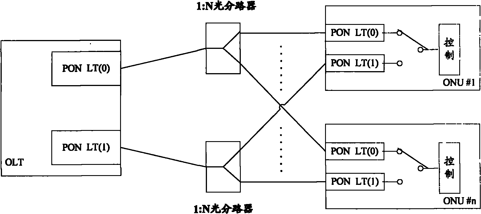
[0035] The basic thought of the present invention is: when the PON port of OLT receives the ONU registration request, distribute unique LLID for ONU, in this PON port, record the state of the LLID of the ONU that requests registration to be online, and another PON of OLT In the port (standby PON port), the state of the LLID of the ONU that records the request to register is offline. When performing dynamic bandwidth allocation for the main and standby PON port LLID of the OLT, normal dynamic bandwidth allocation is performed for the online LLID, while For the online LLID, the dynamic bandwidth allocation is carried out according to the set cycle. The set cycle is very short, so that when the optical fiber link is switched, the standby PON port can quickly realize the rapid ranging of the ONU that was not online, so as to Make the ONU switch to the standby PON port as soon as possible. The switching time of the optical fiber link in the present invention is relatively short, an...


PUM


Abstract

The invention discloses a protection switching method in an Ethernet passive optical network, which comprises the following steps of: synchronizing in real time configuration data between an active port and a standby port of an optical line terminal (OLT); and performing dynamic bandwidth allocation on logical link identifiers (LLID) in the active and standby ports, performing normal dynamic bandwidth allocation on online LLIDs and performing the dynamic bandwidth allocation on offline LLIDs according to a set period by using the OLT. The invention simultaneously discloses a protection switching device in the Ethernet passive optical network, which comprises a synchronization unit used for realizing the real-time synchronization of the configuration data between the active and standby ports of the OLT, and a dynamic bandwidth allocation unit used for performing the dynamic bandwidth allocation on the LLIDs in the active and standby ports, performing the normal dynamic bandwidth allocation on the online LLIDs and performing the dynamic bandwidth allocation on the offline LLIDs according to the set period. The method and the device have the advantages of maximally reducing influenceto data transmission in the EPON and improving the quality of communication services of the EPON.

Description

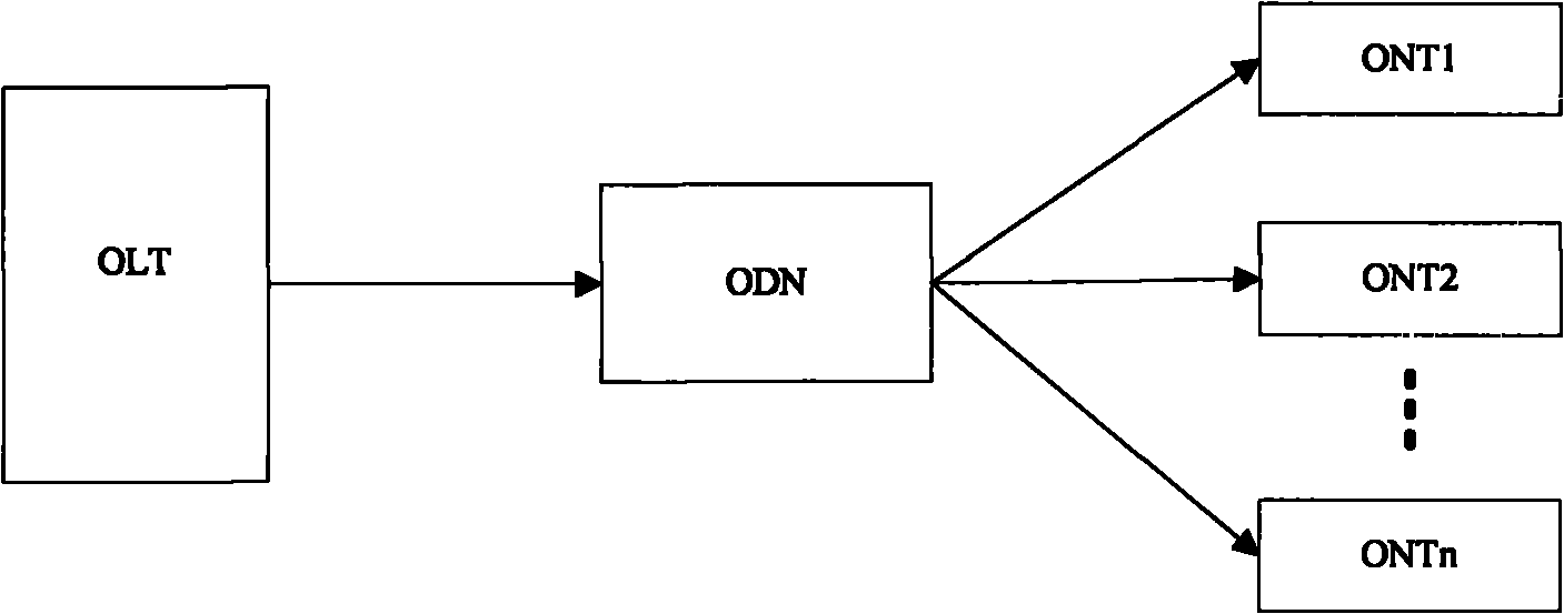
technical field [0001] The invention relates to protection switching technology of redundant ports, in particular to a protection switching method and device in an Ethernet Passive Optical Network (EPON, Ethernet Passive Optical Network). Background technique [0002] The Ethernet passive optical network system is a single-fiber bidirectional optical access network using a point-to-multipoint structure. It consists of an optical line terminal (OLT, Optical Line Terminal) at the central office, an optical network unit (ONU, Optical Line Terminal) Network Unit) and Optical Distribution Network (ODN, Optical Distribution Network). figure 1 It is a schematic diagram of the composition structure of the Ethernet passive optical network, such as figure 1 As shown, because the typical topology of the EPON system is a tree, there is a hidden danger of a single point of failure. If the backbone optical fiber fails, it will cause all the connected ONUs to have faulty communication at...

Claims


Application Information

Patent Timeline
Patent Type & Authority Applications(China)
IPC IPC(8): H04Q11/00H04L12/56H04J3/06H04B10/038
Inventor 胡丹谢云鹏于金辉
Owner ZTE CORP
Learn More