
U-shaped automatic piece wrapping machine for pole pieces of storage batteries

An automatic wrapping machine and storage battery technology, which is applied in the field of wrapping machines, can solve the problems of not getting rid of manual operation, etc., and achieve the effects of reducing hazards and improving wrapping efficiency and quality

Inactive Publication Date: 2010-12-01
ZHEJIANG HAIYUE AUTOMATIC MACHINERY
View PDF7 Cites 47 Cited by
  • Summary
  • Abstract
  • Description
  • Claims
  • Application Information

AI Technical Summary

Problems solved by technology

Therefore, compared with the traditional wrapping method, the above-mentioned patent only relies on the machine to automatically complete the wrapping process of the separator paper on the pole piece, and the pole piece feeding and assembly process has not yet got rid of the manual operation mode.

Method used


Image

  • U-shaped automatic piece wrapping machine for pole pieces of storage batteries
  • U-shaped automatic piece wrapping machine for pole pieces of storage batteries
  • U-shaped automatic piece wrapping machine for pole pieces of storage batteries

Examples


Embodiment 1

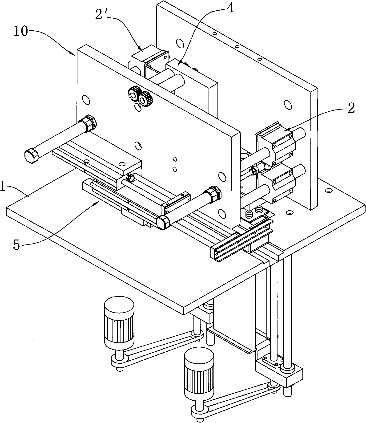
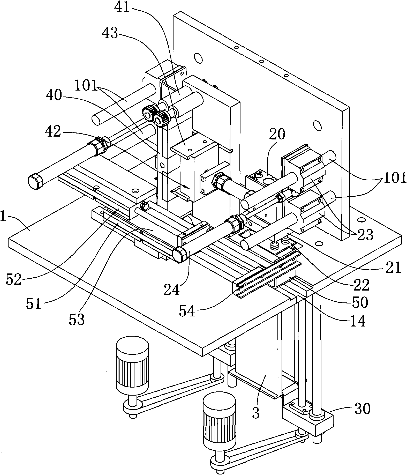
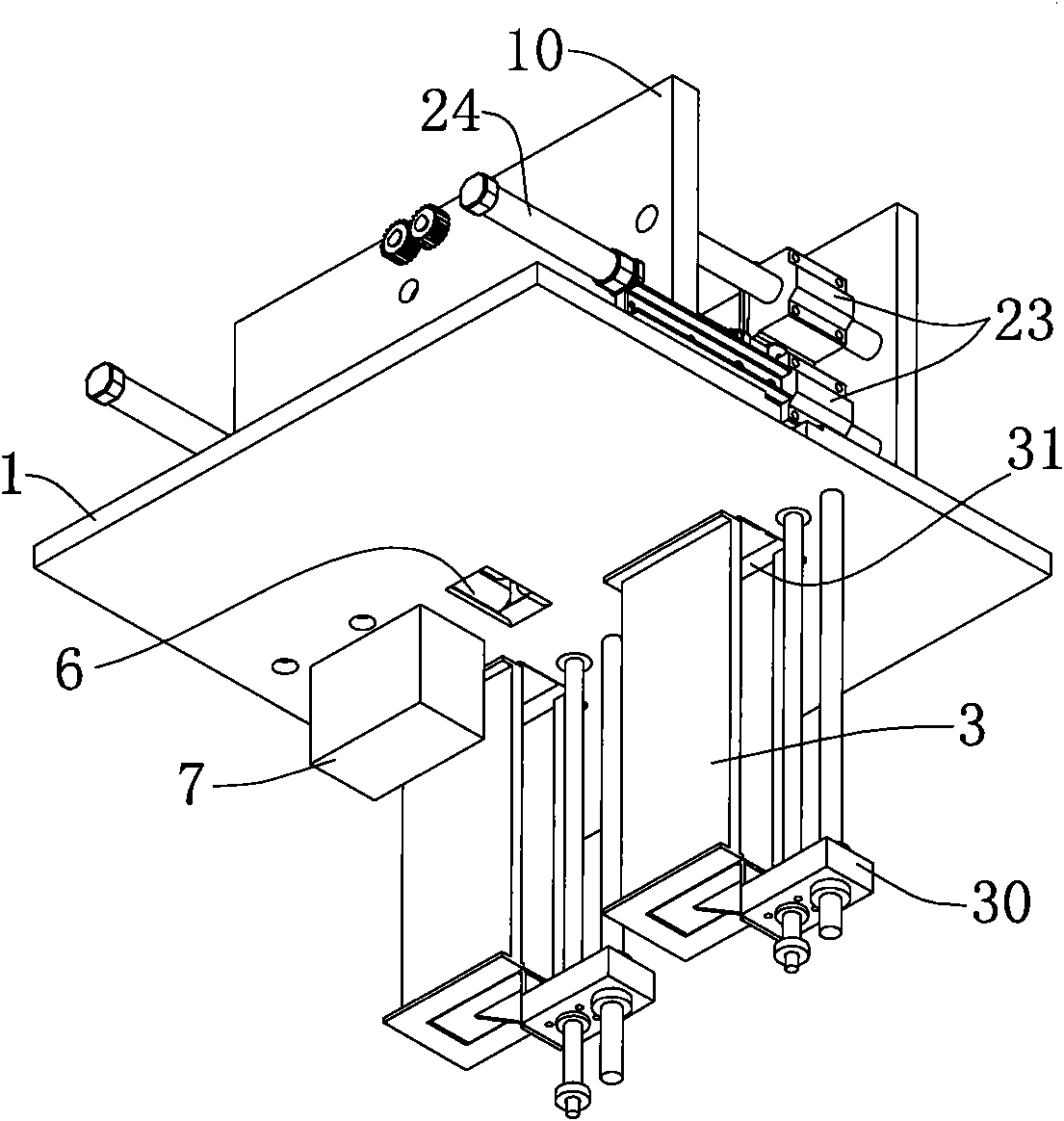
[0028] Embodiment 1: as Figure 5 , Image 6 As shown, the first film supply mechanism and the second film supply mechanism are arranged under the workbench 1, and the workbench 1 is provided with a bracket assembly 10, which communicates with the first film taking port 11 at the discharge end of the first film supply mechanism, and communicates with the second film feeder. The second sheet-feeding port 12 at the discharge end of the sheet-feeding mechanism, the first sheet-feeding mechanism 2 that transfers the first pole piece 7 from the first sheet-taking port 11 to the wrapping mechanism, and the second pole piece 7 are provided in the bracket assembly 10. The sheet 8 is transferred from the second sheet taking port 12 to the second sheet feeding mechanism 2' of the assembly mechanism; both the first sheet feeding mechanism and the second sheet feeding mechanism adopt a box-type feeding structure, and the box-type feeding structure includes a pole piece box 3, One end of ...

Embodiment 2

[0030] Embodiment 2: as Figure 7 As shown, the first sheet feeding mechanism and the second sheet feeding mechanism adopt a roller-type feeding structure and are arranged on the side of the worktable 1; the roller-type feeding structure includes a feeding table 3' and a set Conveyor belt 30' on the feeding table 3'; one end of the conveyor belt of the first film supply mechanism extends to the workbench 1 so that the first pole piece 7 is directly sent to the wrapping mechanism, and one end of the conveyor belt of the second film supply mechanism extends to the workbench 1, the second pole piece 8 is directly sent into the assembly mechanism.

[0031] The first sheet feeding mechanism and the second sheet feeding mechanism in this embodiment have adopted a roller belt feeding structure, which is simpler than Embodiment 1, but takes up a lot of space; the pole piece can be formed by the first sheet feeding mechanism and the second sheet feeding mechanism. The feeding mechanis...


PUM


Abstract

The invention discloses a U-shaped automatic piece wrapping machine for pole pieces of storage batteries, comprising a piece wrapping mechanism for wrapping a first pole piece, an assembly mechanism connected with the discharge end of the piece wrapping mechanism, a first piece supply mechanism for supplying the first pole piece to the piece wrapping mechanism and a second piece supply mechanism for supplying the second pole piece to the assembly mechanism, wherein the second pole piece and the wrapped first pole piece are piled up at intervals in the assembly mechanism to form a pole group. The machine realizes automatic feeding and automatic wrapping of the pole pieces and automatic assembly of the wrapped pole pieces, completes the whole operation process in a streamline manner in one step and improves the wrapping efficiency and quality of the pole pieces. Improvement of the degree of automation is conductive to correspondingly reducing the probability of manually contacting the pole pieces, thus greatly reducing the harm of lead dust to the operators.

Description

technical field [0001] The invention relates to the technical field of battery manufacturing, in particular to a wrapping machine capable of wrapping battery pole pieces and assembling them into pole groups. Background technique [0002] In the current battery production process, there is a process of assembling the positive electrode sheet, negative electrode sheet, and separator paper into an electrode group. The separator paper is sandwiched between the positive electrode sheet and the negative electrode sheet, so the industry usually calls it " In the "wrapping" or "wrapping" process, the way of wrapping is generally divided into U-type, W-type and I-type. However, in the traditional "wrapping" process, manual operations are mostly used. Taking the U-shaped wrapping method as an example, the operator first takes a piece of negative electrode, and wraps both sides of the positive electrode with cut separator paper. The positive electrode sheet is stacked on the negative ...

Claims


Application Information

Patent Timeline
IPC IPC(8): B65B25/14B65B63/00B65B35/10B65B35/18B65B35/20B65B35/24B65B41/02B65B61/00
CPCY02E60/12Y02E60/10Y02P70/50
Inventor 陈义忠
Owner ZHEJIANG HAIYUE AUTOMATIC MACHINERY
Learn More