Light source framework and backlight module

A light source and frame technology, applied in the field of light source frame and backlight module, can solve the problems of long molding cycle, high equipment cost, complex molding process, etc., and achieve the effect of short molding cycle, simple mold and process, and high efficiency

Inactive Publication Date: 2010-12-01
AU OPTRONICS (XIAMEN) CORP +1
View PDF0 Cites 7 Cited by
  • Summary
  • Abstract
  • Description
  • Claims
  • Application Information

AI Technical Summary

Problems solved by technology

[0003] In the existing technology, the embedded design mostly adopts the following methods: 1. Two-color integrated injection molding, but the mold and molding process are complicated, and the equipment cost is high; The yield rate is low; 3. After forming separately, use an ultrasonic welding machine to weld, but you need to purchase ultrasonic welding equipment separately

Method used


Image

  • Light source framework and backlight module
  • Light source framework and backlight module
  • Light source framework and backlight module

Examples


Embodiment Construction

[0021] In order to have a further understanding of the purpose, structure, features, and functions of the present invention, the following detailed descriptions are provided in conjunction with the embodiments.

[0022] The light source frame provided by the present invention can be applied to a backlight module in a liquid crystal display device. The backlight module also includes a light source, such as a lamp tube or an LED light source, which is arranged in the light source frame.

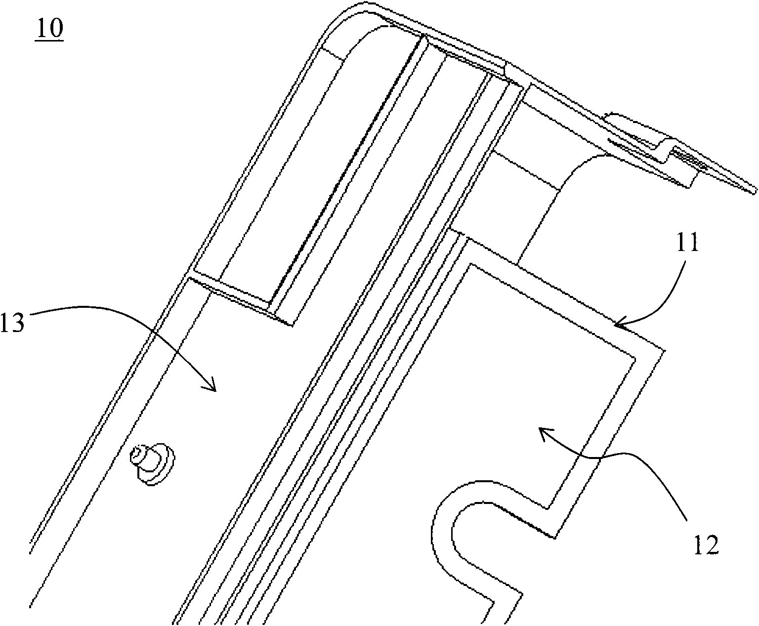
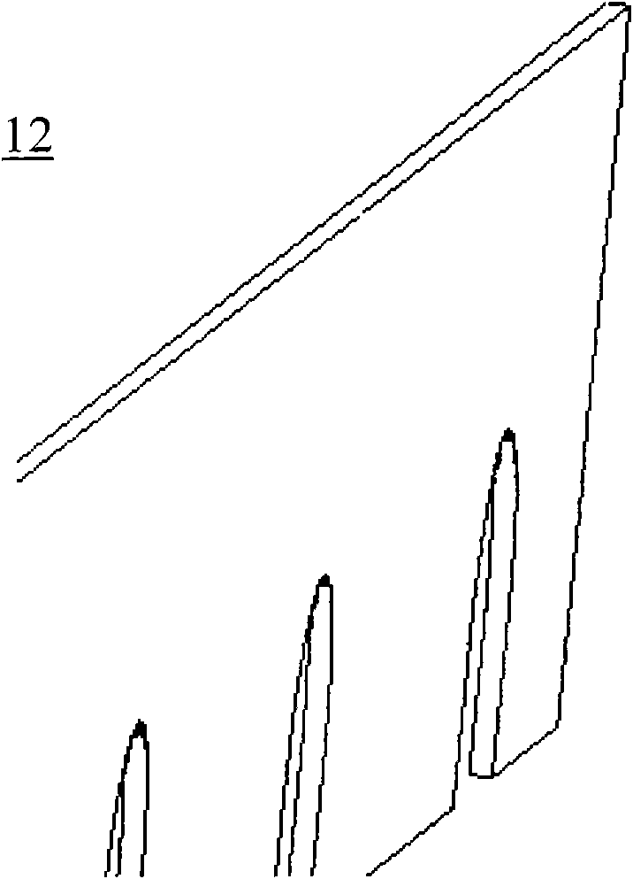
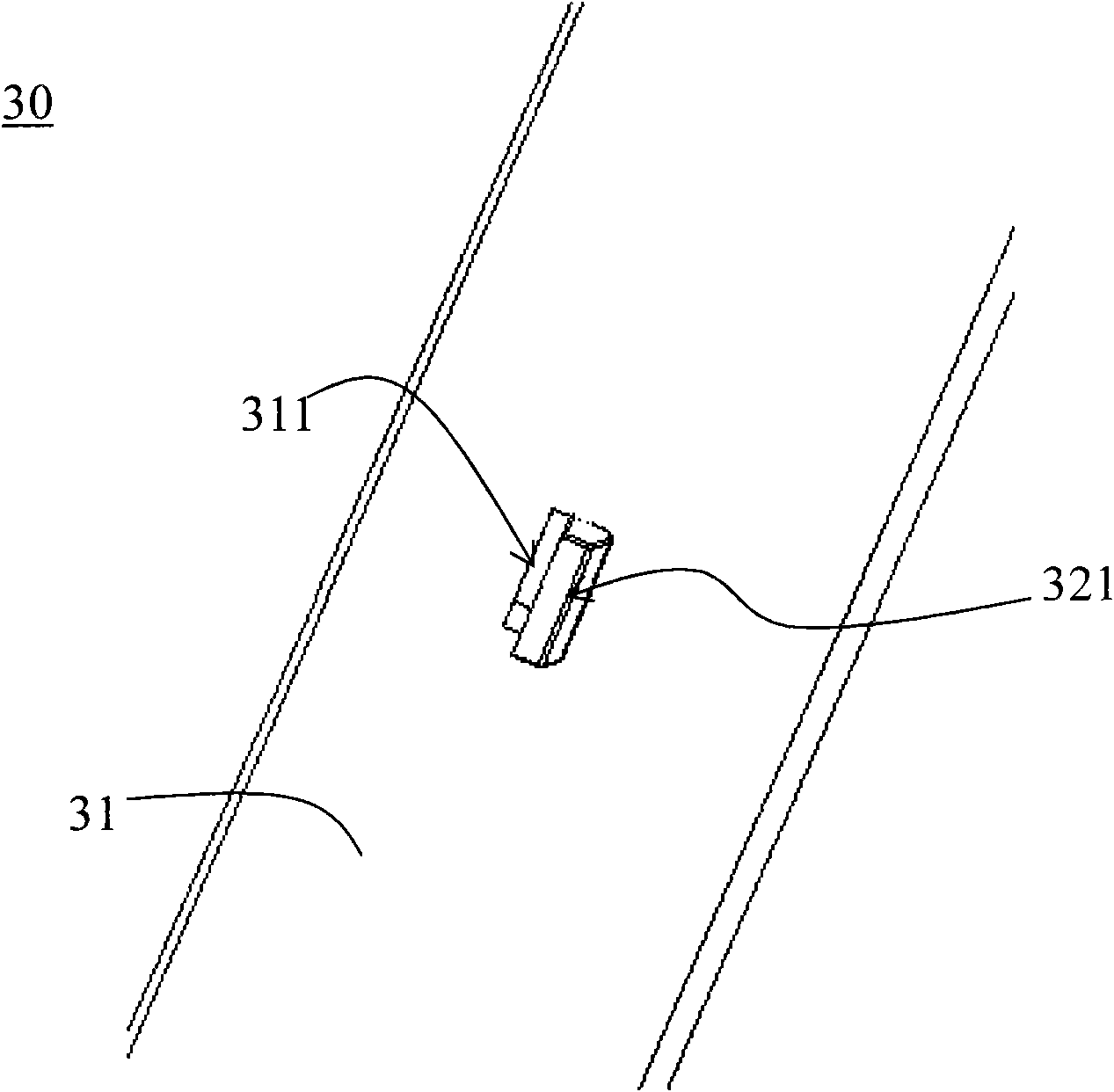
[0023] See image 3 and Figure 4 , image 3 is a schematic diagram of the light source frame 30 of the present invention, Figure 4 for image 3 A schematic diagram of the reflective sheet 32 ​​in . The light source frame 30 includes a frame (not shown), side strips 31 and reflectors 32 (please refer to Figure 4 ,exist image 3 is blocked by the edge strip 31). The side bar 31 is disposed on the frame, and the side bar 31 has at least one positioning hole 311 . The reflective sheet 32...


PUM


Abstract

The invention relates to a light source framework and a backlight module. The light source framework comprises a border, an edge strip and a reflector plate, wherein the edge strip is arranged on the border and provided with at least one positioning hole; the reflector plate comprises a first surface and a second surface; the first surface is an optical reflector surface, and the second surface is provided with at least one hook; and the hooks are matched with the positioning holes and used for fixing the reflector plate onto the edge strip. By adopting the invention, the production efficiency of the backlight module can be improved and the production cost is lowered.

Description

technical field [0001] The present invention relates to a light source frame and a backlight module, in particular to a light source frame and a backlight module applied to a liquid crystal display device. Background technique [0002] At present, due to the demand for cost reduction, the side structure of the frame of the liquid crystal display (LCD) direct-lit backlight module is more and more widely adopting the embedded design of black and white two-color materials. See figure 1 and figure 2 , figure 1 is a schematic diagram of a light source frame 10 in the prior art, figure 2 for figure 1 A schematic diagram of the reflective sheet 12 in . The main structure of the side strip 11 on the frame 13 is black, and the reflection sheet 12 is white, which can reflect the light source and improve the utilization rate of light. [0003] In the existing technology, the embedded design mostly adopts the following methods: 1. Two-color integrated injection molding, but the ...

Claims


Application Information

Patent Timeline
IPC IPC(8): F21V21/00F21V17/10F21V7/10G02F1/13357
Inventor 卢仁生
Owner AU OPTRONICS (XIAMEN) CORP
Why Eureka
Try Eureka