Environment factor monitoring and finite element-based underground power cable current-carrying capacity online prediction system and method

A power cable and environmental factor technology, which is applied in the field of online prediction system of underground power cable ampacity, can solve problems such as inability to accurately predict cable ampacity online, and achieve safe and reliable operation

Inactive Publication Date: 2010-12-01
HEBEI UNIVERSITY OF SCIENCE AND TECHNOLOGY
View PDF4 Cites 19 Cited by
  • Summary
  • Abstract
  • Description
  • Claims
  • Application Information

AI Technical Summary

Problems solved by technology

[0004] The real-time ampacity of the cable is a physical quantity closely related to the cable structure, the thermal conductivity of the surrounding soil, and the surface air. Neither of the above two methods can accurately predict the ampacity of the cable online.

Method used


Image

  • Environment factor monitoring and finite element-based underground power cable current-carrying capacity online prediction system and method
  • Environment factor monitoring and finite element-based underground power cable current-carrying capacity online prediction system and method
  • Environment factor monitoring and finite element-based underground power cable current-carrying capacity online prediction system and method

Examples


Embodiment 1

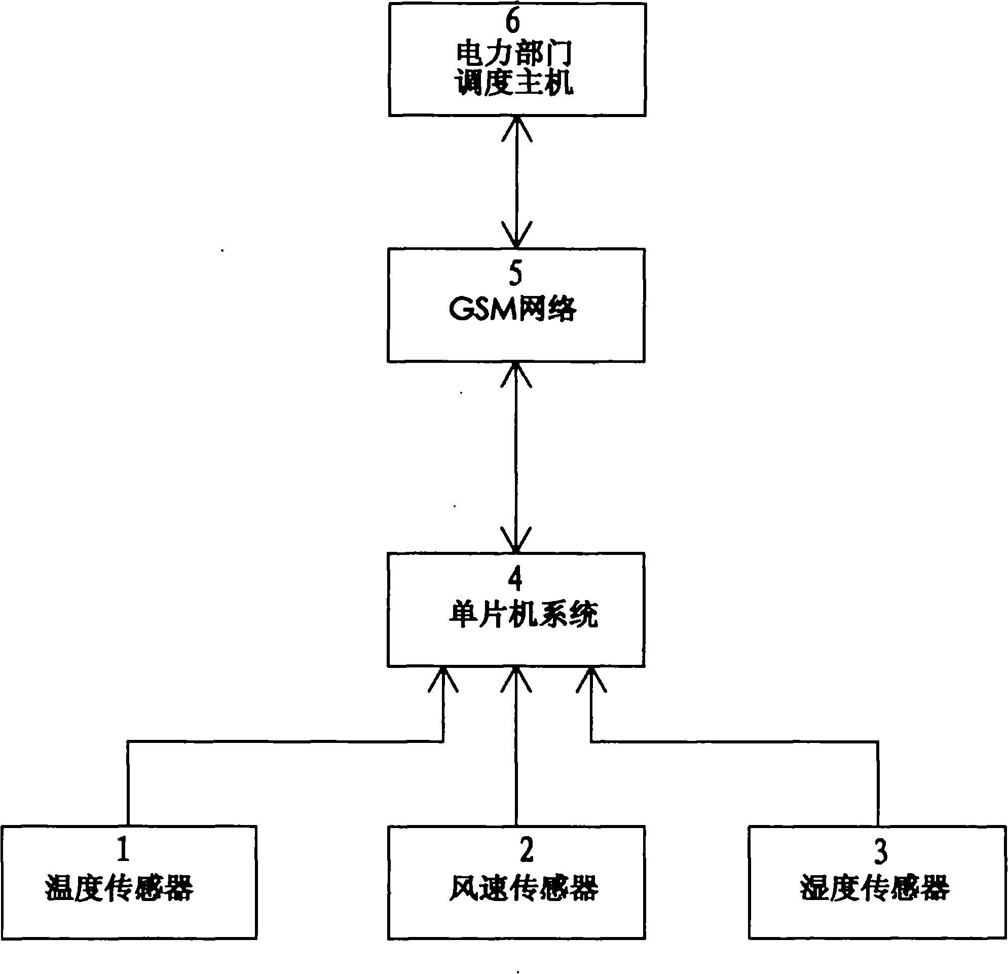
[0043] Embodiment 1 (the embodiment of this system, see figure 1 ,2)

[0044] Present embodiment is made up of the temperature sensor 1 that is used to measure air temperature, wind speed sensor 2, humidity sensor 3, single-chip microcomputer system 4, the dispatching main frame 6 of power sector; The output end of described temperature sensor 1, wind speed sensor 2, humidity sensor 3 Connect the corresponding input ends of the single-chip microcomputer system respectively, and the single-chip microcomputer system is connected with the dispatching host 6 through the GSM network 5; the temperature sensor 1 and the wind speed sensor 2 are installed directly above the power cable, and the humidity The sensor 3 is installed in the soil along the power cable.

Embodiment 2

[0045] Embodiment 2 (the embodiment of this method, see figure 1 , 2, 3):

[0046] The concrete steps of this embodiment are as follows:

[0047] (1) Modeling:

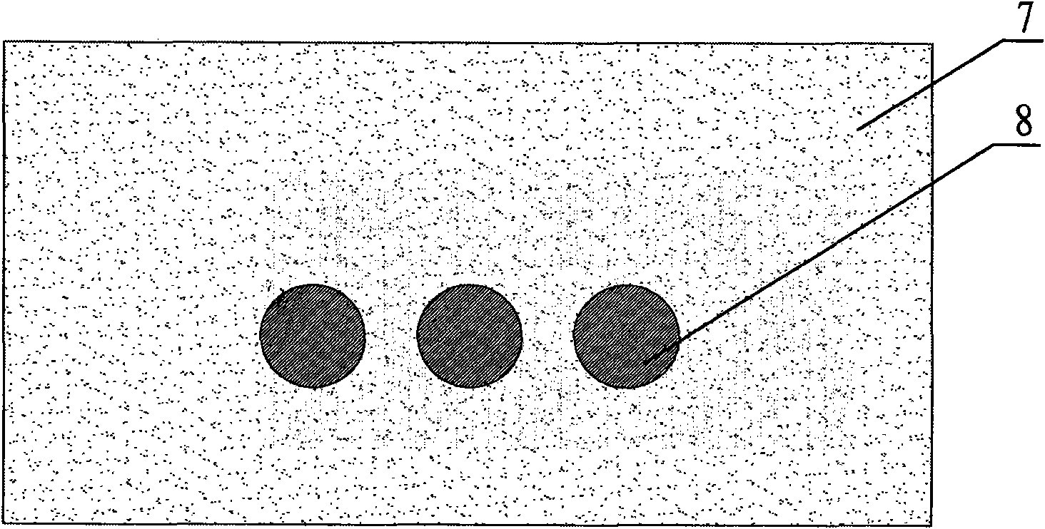
[0048] a. Soil direct buried cable:

[0049] The power cable is 1m away from the ground, and the distance between the two sides of the power cable is 10m from the cable. In the calculation, the heat flow rate of the normal direction of the two sides of the boundary is 0, that is, the soil temperature does not change anymore; the distance between the power cable and the deep soil boundary is 10m. The boundary temperature of the deep soil layer is taken as constant, and the temperature value is the temperature of the deep soil layer, which is 383K;

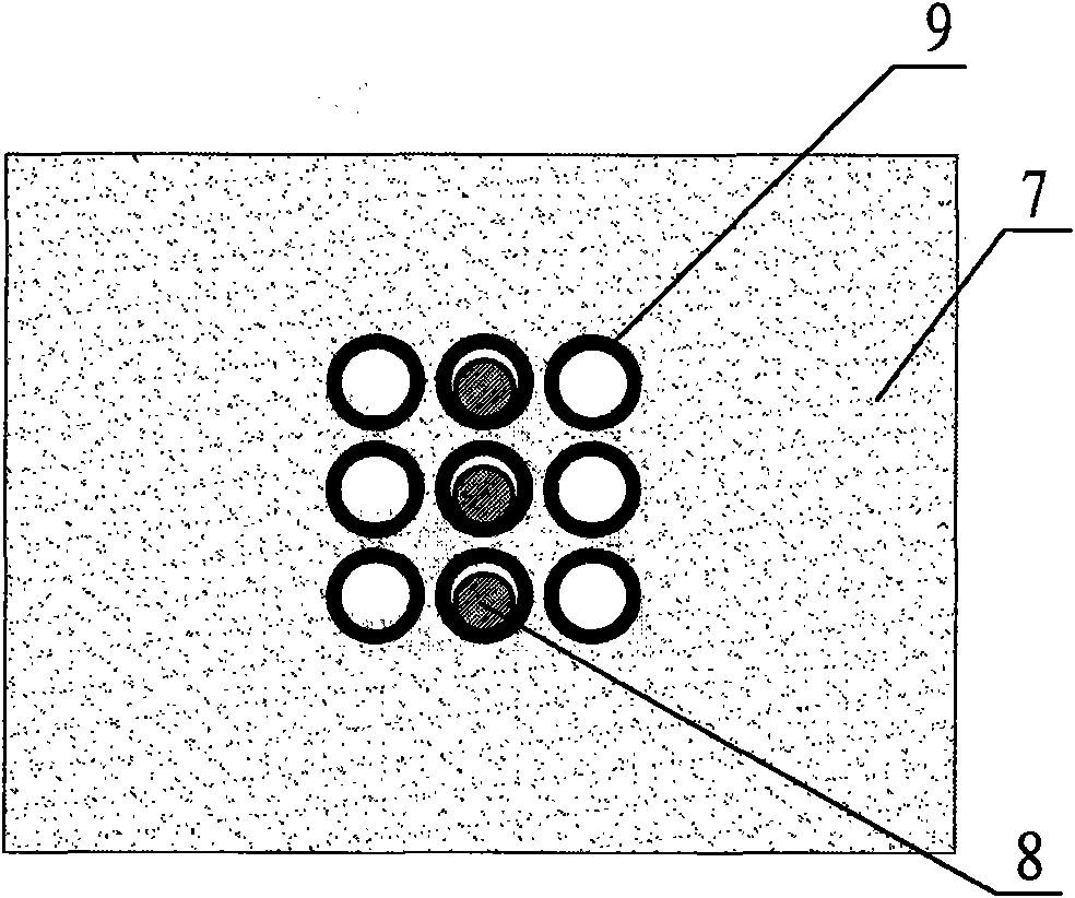
[0050] b. Calandria cable:

[0051] The top of the pipe is 1m from the ground, the power cable is laid in the pipe, and the borders on both sides of the pipe are 10m away from the pipe. In the calculation, the rate of heat flow change in the normal direction of the border...


PUM


Abstract

The invention relates to an environment factor monitoring and finite element-based underground power cable current-carrying capacity online prediction system and an environment factor monitoring and finite element-based underground power cable current-carrying capacity online prediction method. The system consists of a temperature sensor used for measuring the air temperature, a wind speed sensor, a humidity sensor, a singlechip system and a scheduling host of a power department. The method comprises the step of predicting the current-carrying capacity of an underground power cable by combining temperature, wind speed, humidity and other data measured in real time with the calculation of a finite element temperature field. The system and the method have the advantages that: the system and the method can accurately predict the current-carrying capacity of the underground power cable on line, so that the power department can develop the capacity of conveying electric energy to the greatest degree; meanwhile, the system and the method can avoid the resource waste phenomenon of wasting the talent on a petty job on the premise of guaranteeing safe and reliable operation.

Description

technical field [0001] The invention relates to an online prediction system and method for the ampacity of underground power cables based on environmental factor monitoring and finite elements. Background technique [0002] Underground high-voltage power cables are the main form of urban power transmission and distribution lines. Due to their high installation costs and difficult maintenance, on the basis of ensuring their long-term safe and reliable operation, the current carrying capacity of high-voltage power cables should be reasonably determined to maximize Its ability to deliver electrical energy is of great importance to the power sector. [0003] At present, there are two methods for determining the ampacity of underground power cables. One is offline calculation, that is, according to the local soil properties and the highest temperature in the hottest month, according to IEC60287 or finite element calculation; the other is online calculation, through online Monito...

Claims


Application Information

Patent Timeline
Patent Type & Authority Applications(China)
IPC IPC(8): G01R31/00
Inventor 梁永春
Owner HEBEI UNIVERSITY OF SCIENCE AND TECHNOLOGY
Why Eureka
Try Eureka