
Mold core and manufacturing method of micro-optical lens array

A lens array and manufacturing method technology, applied in optics, lenses, optical components, etc., can solve the problems of inaccurate alignment, difficult product qualification rate to meet the requirements of mass production, and unpredictable deviations, so as to improve alignment accuracy Effect

Inactive Publication Date: 2010-12-01
HONG FU JIN PRECISION IND (SHENZHEN) CO LTD +1
View PDF7 Cites 0 Cited by
  • Summary
  • Abstract
  • Description
  • Claims
  • Application Information

AI Technical Summary

Problems solved by technology

[0005] However, since the micro-optical lens mold core and the alignment marks on it are usually manufactured by ultra-precision processing technology, the line width is about 100 microns, and the marks manufactured on the silicon wafer are produced by lithography ( lithography), its size can be accurate to 1 micron, so the two marks differ by two orders of magnitude, resulting in the inaccurate alignment of the micro-optical lens mold core and the silicon wafer; in addition, it is impossible to predict how large the deviation is when manufacturing the micro-optical lens , the position deviation during manufacturing can only be calculated according to the distribution of products on the silicon wafer after the production is completed, and then this deviation will be taken into account in the next production, so as to align the mold core and the silicon wafer as much as possible
However, this method obviously brings a high defective rate, and the pass rate of the product is difficult to meet the requirements of mass production.

Method used


Image

  • Mold core and manufacturing method of micro-optical lens array
  • Mold core and manufacturing method of micro-optical lens array
  • Mold core and manufacturing method of micro-optical lens array

Examples


Embodiment Construction

[0015] The present invention will be further described in detail below in conjunction with the drawings.

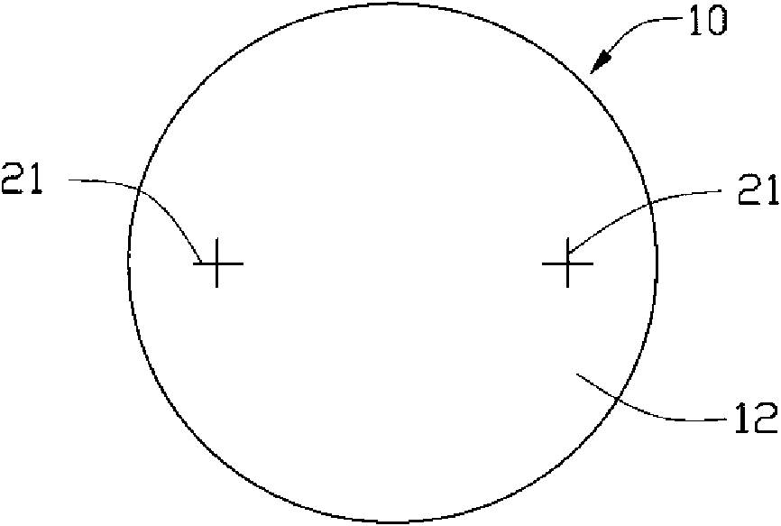
[0016] See figure 1 In the first embodiment of the present invention for manufacturing a micro-optical lens array, a metal plate 10 is first provided. The metal plate 10 has a circular first surface 12 with a diameter of 8 mm, and two first marks 21 are made on the first surface 12 by a photolithography process. Each first mark 21 is in the shape of a "cross". Theoretically, the first mark 21 can be located at any position on the first surface 12. The relative positional relationship between the two first marks 21 can also be arbitrary, but preferably, two The first mark 21 is substantially located at the center of the first surface 12 and is arranged symmetrically with respect to the center of the first surface 12, so that such a mark is easy to identify.

[0017] Preferably, the line width of the first mark 21 produced by the photolithography process is controlled to be 10 ...


PUM

PropertyMeasurementUnit
widthaaaaaaaaaa
widthaaaaaaaaaa

Abstract

The invention provides a manufacturing method of a micro-optical lens array, comprising the following steps of: providing a mold core, wherein the mold core is provided with a first surface, and the first surface is provided with a first mark manufactured by a lithography procedure, a mold cavity and a second mark which are manufactured in an ultraprecision machining way; measuring offset value of the second mark relative to the first mark; providing a substrate with a second surface; manufacturing a third mark on the second surface by the lithography procedure, wherein the position of the third mark on the second surface is the same as the position of the first mark on the first surface; firstly aligning the third mark to the first mark; secondly moving the substrate according to the offset value to align the third mark to the second mark; and applying forming materials onto the mold core or the substrate, and printing and forming the micro-optical lens array. The invention further provides a mold core. The mold core and the manufacturing method of the micro-optical lens array can improve the aligning precision and the product yield.

Description

Technical field [0001] The invention relates to the manufacturing field of optical elements, in particular to a mold core used for imprinting and molding a micro-optical lens array and a manufacturing method of the micro-optical lens array. Background technique [0002] With the development of optoelectronic products, micro-optical lenses have become a fundamental element in the optoelectronic industry because they can produce optical effects in a small area. For example, the backlight of a liquid crystal display uses an optical lens array to achieve the effect of uniformizing the backlight. Therefore, the technology of using various manufacturing processes to manufacture micro-optical components has become a technology that is being developed by all walks of life. [0003] At present, there are many methods for manufacturing micro-optical lens arrays. [0004] The method is generally to coat a molding material on a substrate, such as a silicon wafer, press a prefabricated micro-op...

Claims


Application Information

Patent Timeline
Patent Type & Authority Applications(China)
IPC IPC(8): G02B3/00G03F7/00
CPCB82Y10/00G02B3/0031B82Y40/00G03F7/0002
Inventor 骆世平
Owner HONG FU JIN PRECISION IND (SHENZHEN) CO LTD
Features
  • Generate Ideas
  • Intellectual Property
  • Life Sciences
  • Materials
  • Tech Scout
  • Unparalleled Data Quality
  • Higher Quality Content
  • 60% Fewer Hallucinations
Learn More