Transfer apparatus, image forming apparatus, and image forming method
What is AI technical title?
AI technical title is built by PatSnap AI team. It summarizes the technical point description of the patent document.
An image and transfer member technology, applied in the field of transfer devices, can solve the problems of stress concentration skew and shortened life, and achieve the effects of preventing accumulated skew, reducing offset, and reducing skew
Inactive Publication Date: 2010-12-01
SEIKO EPSON CORP
View PDF1 Cites 1 Cited by
Summary
Abstract
Description
Claims
Application Information
AI Technical Summary
This helps you quickly interpret patents by identifying the three key elements:
Problems solved by technology
Method used
Benefits of technology
Problems solved by technology
In the case of using such an elastic member, there is a problem that distortion due to stress concentration is likely to occur.
In addition, as a result, the inconvenience that life shortens occurs
Method used
Image
Click on the blue label to locate the original text in one second.
Reading with bidirectional positioning of images and text.
Examples
Embodiment 1
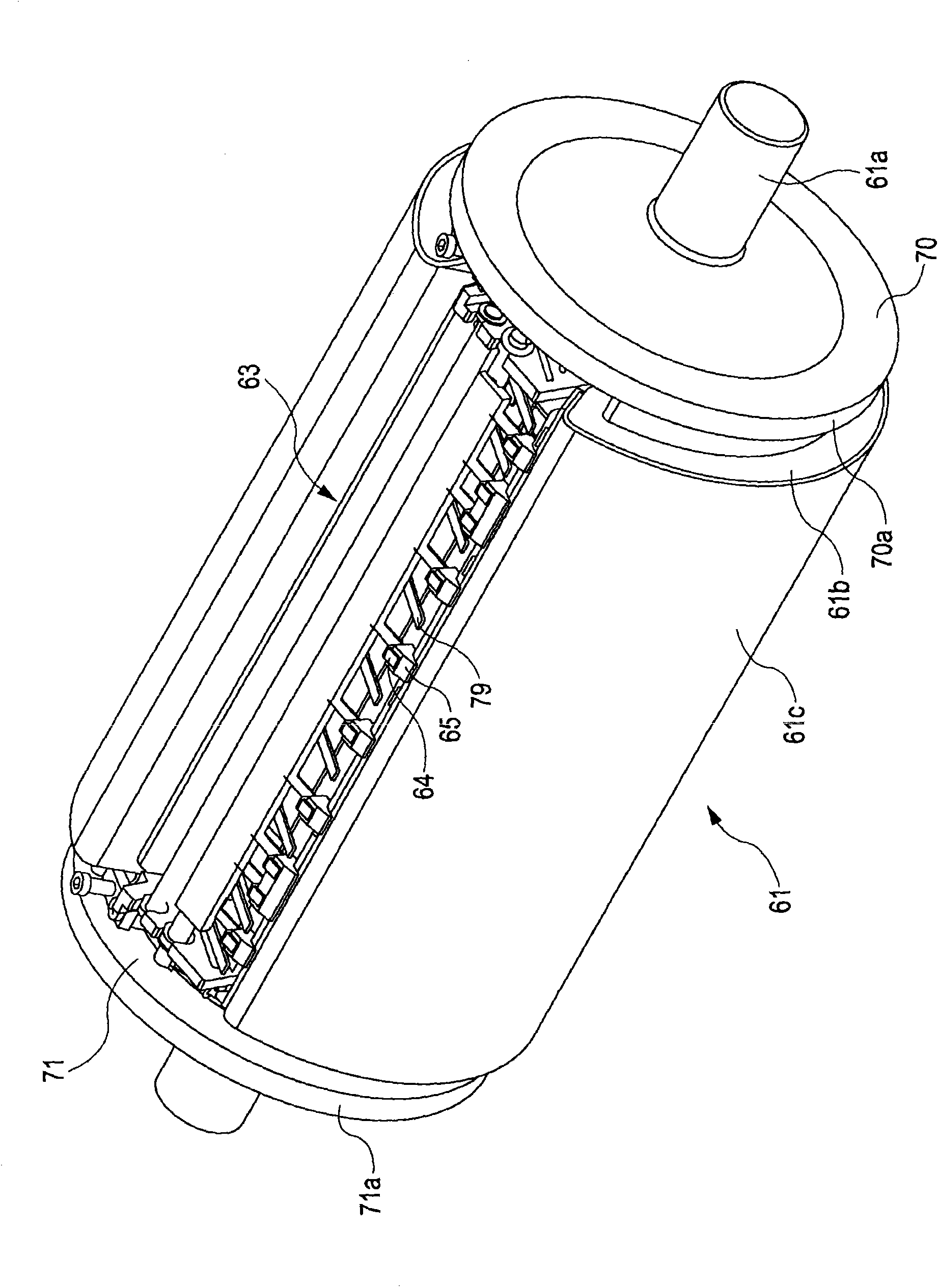
[0105] The rubber sheet 61c of Example 1 has the following structure.
[0116] Conductive material: Electron conductive material (carbon)
[0117] As a result of using such a rubber sheet 61c and the intermediate transfer belt 40 in the image forming apparatus of the first embodiment having a single-pinch structure, the secondary transfer property to coated paper can be improved.
Embodiment 2
[0119] The rubber sheet 61c of Example 2 has a two-layer structure and has the following structure.
[0131] In addition, the Young's modulus of the rubber sheet 61c should just be 2-5 GPa. In addition, the conductive material of the rubber sheet 61c may be a mixed conductive material containing an ion conductive material or an electronic conductive material (carbon) and an ion conductive material. Furthermore, the rubber hardness may be 30° to 70°.
[0132] In addition, the intermediate transfer belt 40 of Example 2 has ...
PUM
Abstract
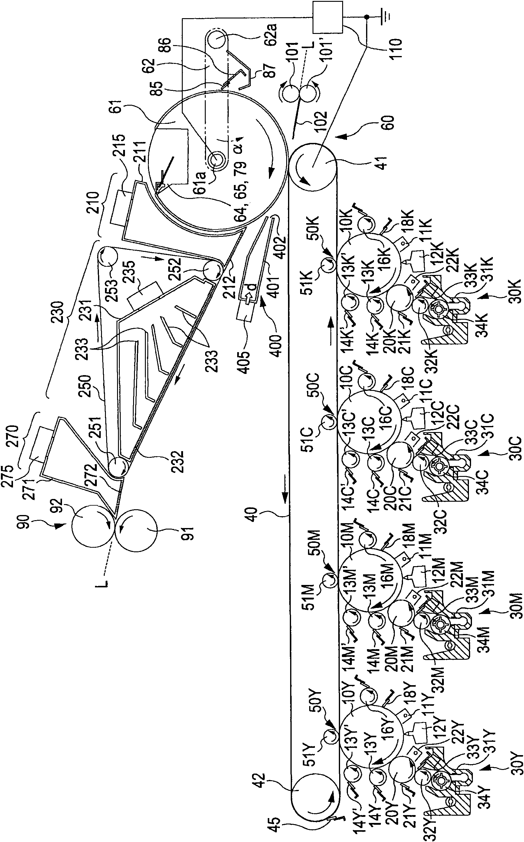
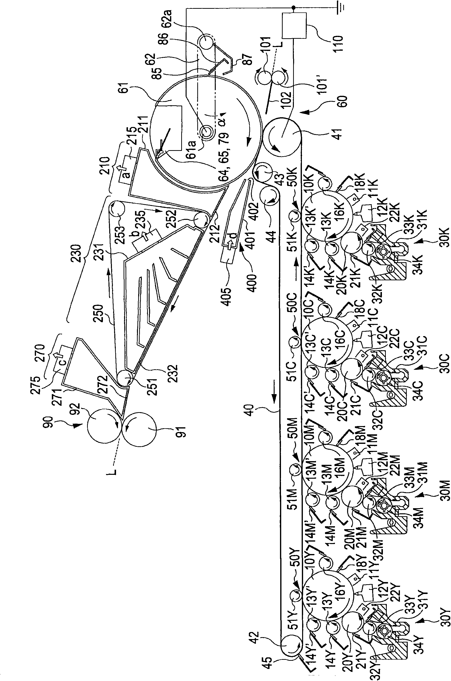
The invention provides a transfer apparatus excellently performing transfer by reducing distortion of an elastic layer of a transfer roller and transfer defect involved with the distortion and to provide an image forming apparatus excellently forming an image and an image forming method. The transfer apparatus includes: image carriers 10Y, 10M, 10C and 10K carrying the image; a transfer member 61 including a base material 61b having a recessed portion 63 having an opening width longer than the width of a nip portion formed with the image carriers in the moving direction of the image carriers 10Y, 10M, 10C and 10K and an elastic member 61c which is fixed by the recessed portion 63 and wound around the base material 61b and whose volume resistivity is 1*10<SP>6< / SP>-1*10<SP>11< / SP>[Omega]cm; and a bias generating portion 110 applying a bias to the nip portion.
Description
technical field [0001] The present invention relates to a transfer device, an image forming device and an image forming method related to electrophotography. Background technique [0002] Conventionally, it has been disclosed that a transfer roller having an elastic layer is used as a transfer roller of an image forming apparatus (Patent Document 1). The image forming apparatus described in Patent Document 1 describes the shape considered to be a concave portion, but does not mention its function. In addition, as the transfer method, only the thermal transfer method is described, but the bias transfer method is not described. [0003] [Patent Document 1]: Special Publication No. 2000-508280 [0004] However, since the transfer method of Patent Document 1 is a thermal transfer method, the present invention is a bias transfer method, and therefore, it is necessary to impart electrical resistance to the elastic member of the transfer member. When such an elastic member is us...
Claims
Application Information
Patent Timeline
Application Date:The date an application was filed.
Publication Date:The date a patent or application was officially published.
First Publication Date:The earliest publication date of a patent with the same application number.
Issue Date:Publication date of the patent grant document.
PCT Entry Date:The Entry date of PCT National Phase.
Estimated Expiry Date:The statutory expiry date of a patent right according to the Patent Law, and it is the longest term of protection that the patent right can achieve without the termination of the patent right due to other reasons(Term extension factor has been taken into account ).
Invalid Date:Actual expiry date is based on effective date or publication date of legal transaction data of invalid patent.

