Control system for low-speed running of permanent magnet motor

A control system and permanent magnet motor technology, applied in the direction of torque ripple control, etc., can solve the problems of no consideration of influence, large error, and reduced response speed of the control system, so as to achieve increased response speed, increased stability, and good adaptability Effect

Active Publication Date: 2010-12-01
SHANGHAI INST OF TECHNICAL PHYSICS - CHINESE ACAD OF SCI
6 Cites 14 Cited by

AI-Extracted Technical Summary

Problems solved by technology

[0003] The disadvantage of this control system is that it does not consider the influence of other resistance torques except cogging torque
Since the cogging torque is a periodic disturbance, other resistance torques such as friction torque or elastic resistance torque can be regarded as non-periodic disturbances. The impact of non-periodic disturbances on the delay of the control system is not the same as that of periodic disturbances. A single estimate The device cannot accurately ...

Abstract

The invention discloses a control system for low-speed running of a permanent magnet motor, which consists of a speed controller, a current loop, an angle sensor, a disturbing estimator, a tooth socket torque estimator and a tooth socket torque calculator. The sizes of the tooth socket torque and the rest resisting moments are quickly calculated by the disturbing estimator and the tooth socket torque estimator; the influence of the tooth socket torque on the speed is further accurately calculated through the tooth socket torque calculator so as to make compensation; the stability of the control system is increased by controlling integral coefficients of the speed controller in real time, and equivalently, output current is changed through changing the integral coefficients to compensate for aperiodic resisting moments at the same time; and the response speed of the control system is increased by carrying out the advanced compensation of the delay of the controller so that the disturbance is quicker to attenuate. The control system has higher correctness and stability, and is particularly suitable for realizing the low-speed control of the permanent magnet motor under the condition of the larger change range of the resisting moments.

Application Domain

Technology Topic

Velocity controllerIntegral coefficient +6

Image

  • Control system for low-speed running of permanent magnet motor
  • Control system for low-speed running of permanent magnet motor
  • Control system for low-speed running of permanent magnet motor

Examples

  • Experimental program(1)

Example Embodiment

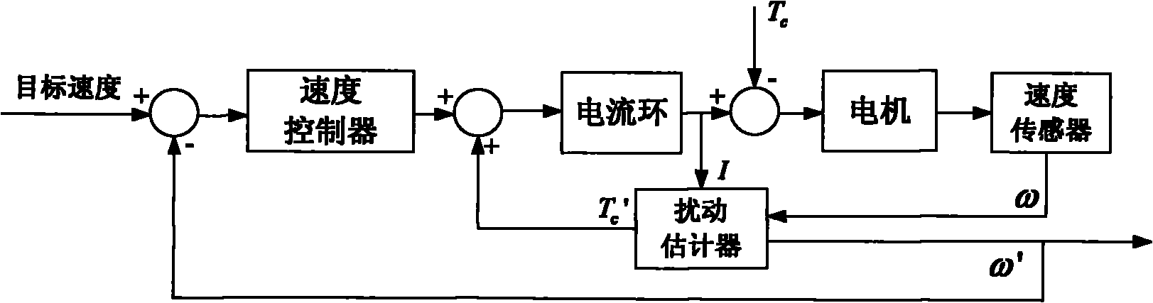
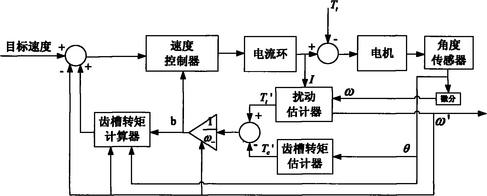
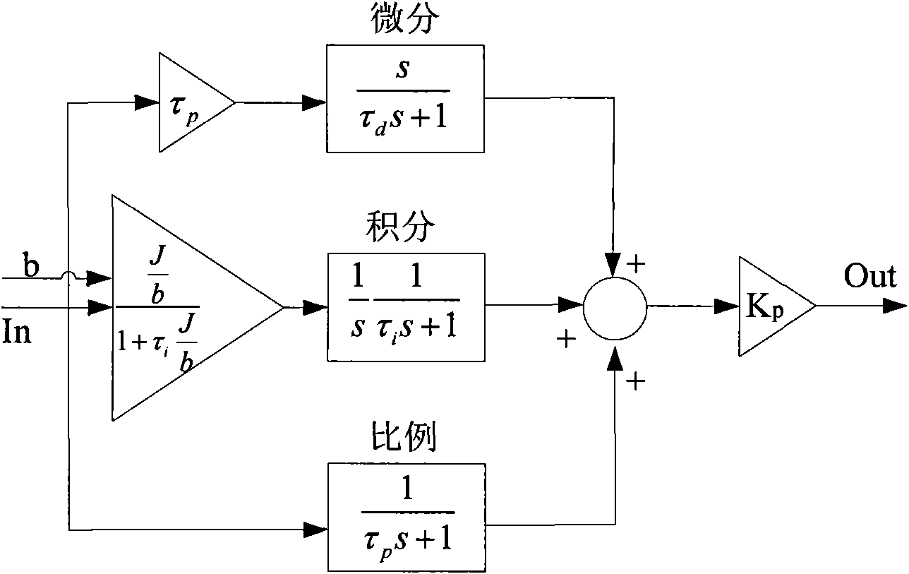
[0020] 1. According to figure 2 The block diagram shown to build the control system; the block diagram of the adaptive PID controller is as image 3 As shown; the block diagram of the disturbance estimator is as Figure 4 Shown; the feedback speed ω of the outermost loop of the control system - Either the estimated speed ω'or the measured speed ω can be used. Generally, if the resolution of the sensor is high enough, the output of the estimator can be used as feedback. If the resolution of the sensor is not high but the response is fast enough, the speed derived from the sensor can be used As feedback.
[0021] 2. Select the pole op of the disturbance estimator 1 And op 2 , You can make op 1 =op 2 And choose 2-6 times the pole corresponding to the 3dB bandwidth of the control system; use the acker function of Matlab software to calculate the feedback gain g required by the disturbance estimator 1 And g 2 , The use of acker function is:
[0022] [g 1 g 2 ]=acker(A′,B′,op) (6)
[0023] among them
[0024] A′=[0 0; -1/J 0]
[0025] C′=[1;0]
[0026] op=[op 1 op 2 ]
[0027] 3. Disconnect the cogging torque estimator and the cogging torque calculator from the loop, and adjust the PID controller to determine the best proportional coefficient K p The value of is also determined by the root locus diagram of the open-loop transfer function. Let the control system control the motor to run at a uniform speed. The speed can be more than 10 times the actual working speed. According to formula (5), when the speed is high enough, b in the denominator 2 The term can be ignored, collecting the output angle θ and feedback speed ω of the angle sensor - , With θ as the abscissa ω - Draw a graph for the ordinate and record the peak ω of the graph m , Mean Period T θ And when the feedback speed ω - Equal to mean And the slope is any angle value θ when the c0 , Then the spatial distribution of cogging torque N p , Cogging torque zero point θ 0 And peak cogging torque T cm The value of can be determined by the following formula:
[0028] N p = 2 π T θ - - - ( 7 )
[0029] θ 0 = N p θ c 0 - π 2 N p - - - ( 8 )
[0030] T cm =JN p ω m (9)
[0031] Several sets of limits can be measured at different speeds to determine the peak cogging torque T cm Value.
[0032] 4. Connect the cogging torque estimator and cogging torque calculator into the loop to form a complete control system. The expression of the cogging torque estimator is (2), and the cogging torque calculator is The expression is (5).

PUM

no PUM

Description & Claims & Application Information

We can also present the details of the Description, Claims and Application information to help users get a comprehensive understanding of the technical details of the patent, such as background art, summary of invention, brief description of drawings, description of embodiments, and other original content. On the other hand, users can also determine the specific scope of protection of the technology through the list of claims; as well as understand the changes in the life cycle of the technology with the presentation of the patent timeline. Login to view more.

Similar technology patents

Dual-CPU based circuit breaker intelligent controller

Owner:WUHAN NARI LIABILITY OF STATE GRID ELECTRIC POWER RES INST

Classification and recommendation of technical efficacy words

  • Improve stability
  • Reduce mistakes

Gel stabilized nanoparticulate active agent compositions

ActiveUS20050031691A1Improve stabilityImprove dissolutionPowder deliveryBiocideActive agentAverage diameter
Owner:ALKERMES PHARMA IRELAND LTD

Surgical ligature clip

InactiveUS20080312670A1Improve stabilityAvoid spaceWound clampsOrthodontic ligatureArm moving
Owner:AESCULAP AG

Terminal positioning track fitting method based on Bezier curve

ActiveCN102998684AReduce mistakesSatellite radio beaconingSatellite navigationFitting methods
Owner:XIAMEN YAXON NETWORKS CO LTD

Multifunctional road soil roadbed freezing and thawing circulating test device

ActiveCN101923085ASolving Elasticity ProblemsReduce mistakesRoadwaysEarth material testingTest measurementFrost
Owner:CCCC SECOND HIGHWAY CONSULTANTS CO LTD
Why Eureka
Try Eureka