Rigid connection method for steel beam and concrete pier

A rigid connection, reinforced concrete technology, used in bridges, bridge construction, erection/assembly of bridges, etc., can solve the problems of low rigidity and bearing capacity, complicated construction, complicated construction process, etc., to improve strength and ductility, construction convenience, Construct simple effects

Active Publication Date: 2010-12-08
TSINGHUA UNIV
View PDF10 Cites 14 Cited by
  • Summary
  • Abstract
  • Description
  • Claims
  • Application Information

AI Technical Summary

Problems solved by technology

Reinforcement-anchored joints rely on the main reinforcement in the pier to be anchored in the main girder to transmit force, which requires a long anchorage length of the main reinforcement. The construction process is complicated and it is difficult to ensure the pouring quality of the concrete in the core area of ​​the joint; The steel plate is connected with the steel bar of the main pier, and the force is transmitted directly. The core area of ​​the node is a pure steel structure, and its rigidity and bearing capacity are low; The corbel is buried in the pier to form an overall force, and its overall work performance is good, but the construction is relatively complicated, and the steel bars and steel frames in the joint area are interlaced, which affects the pouring quality of the concrete in the joint core area

Method used


Image

  • Rigid connection method for steel beam and concrete pier
  • Rigid connection method for steel beam and concrete pier
  • Rigid connection method for steel beam and concrete pier

Examples


Embodiment Construction

[0017] The specific embodiments of the present invention will be further described below in conjunction with the accompanying drawings.

[0018] Construction procedure of the present invention is:

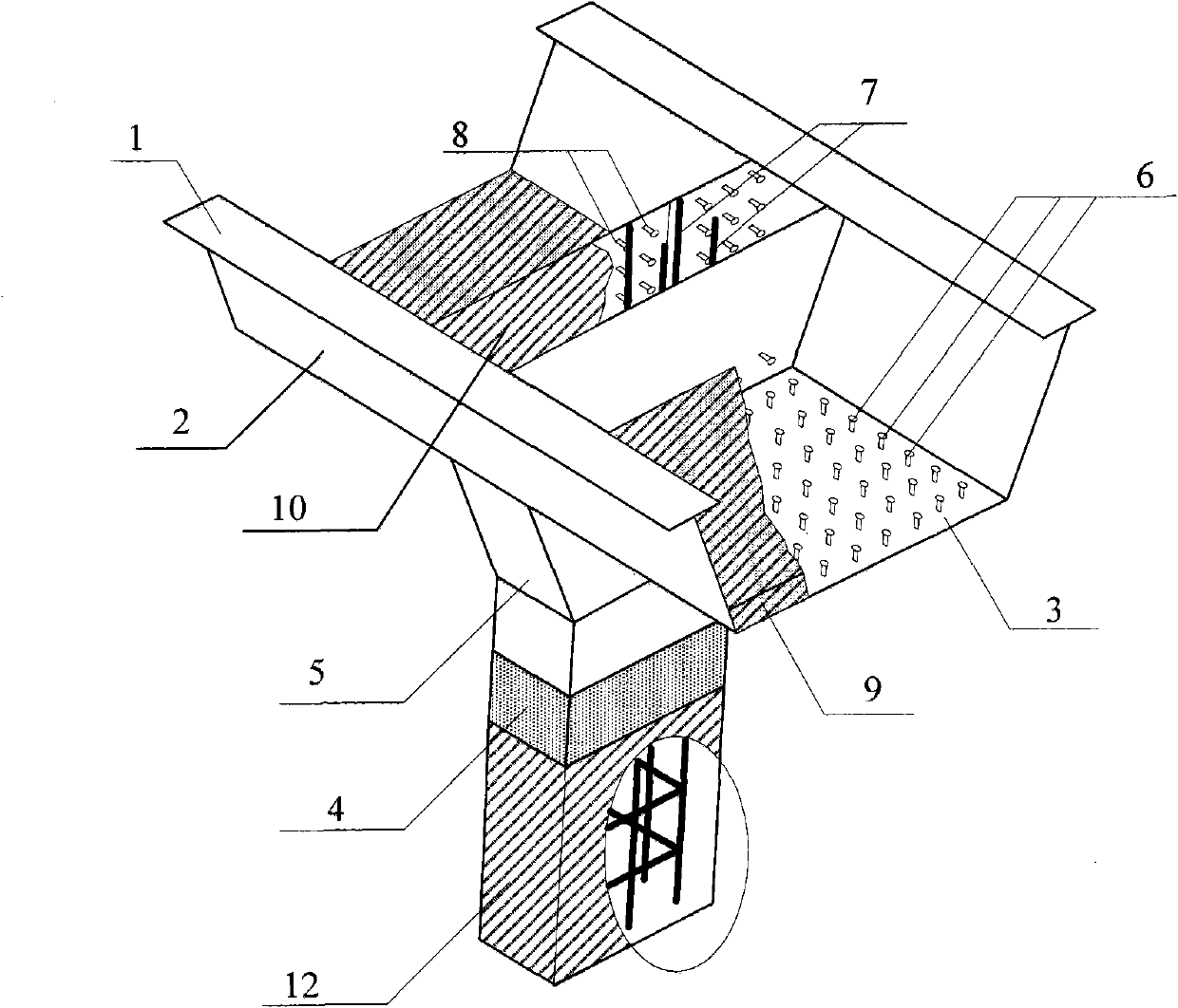
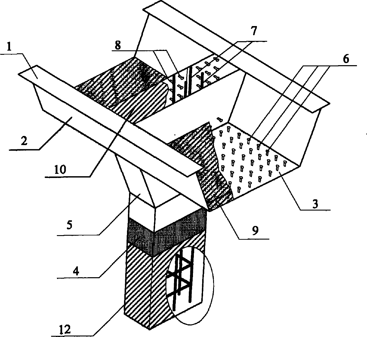
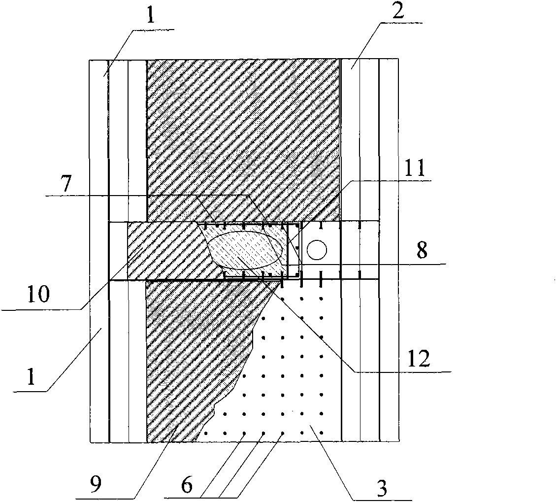
[0019] 1) Weld the steel girder upper flange (1), steel girder bottom plate (3) and steel girder web (2) into a whole, wherein the steel girder bottom plate (3) has holes in the joint area, and a sleeve is extended under the steel girder bottom plate Tube (5) is welded together with steel beam bottom plate (3). Weld the studs (6) on the steel beam bottom plate (3), weld the studs (8) on the inside of the steel beam overhanging sleeve (5), and weld the studs (8) on the inside of the steel beam overhanging sleeve (5) and the steel beam bottom plate (3) Weld the inner partition steel plate (11) of the opening at the equal height opening;

[0020] 2) Install the steel sleeve (4) at the top of the reinforced concrete pier to the top of the pier, and pour the pier concrete (12) so that...


PUM


Abstract

The invention discloses a rigid connection method for a steel beam and a concrete pier, and belongs to the technical field of bridgework and combined structures. The rigid connection method is characterized in that: a steel sleeve extending outwards is arranged under a steel main beam; a steel sleeve is arranged on the top of a pier; the pier and the beam are fixedly connected through the connection between the steel sleeves; and the inner walls of the steel sleeves are provided with stud connecting pieces to prevent the steel sleeves from locally flexing and facilitate coaction of the steel sleeves and the concrete. The rigid connection method comprises the following steps of: hoisting the main beam provided with the steel sleeve extending outwards to the top of the pier with the steel sleeve, and taking connection measures; positioning a reinforcement cage in a pillar, and casting the concrete to the lower side of the upper wing edge of the main beam to form rigid connection nodes. The axial force on the top of the pier is mainly borne and transmitted through the concrete in a node core area; the bending moment of the top of the pier is mainly borne and transmitted through a diaphragm plate, tensioned steel bars and the concrete in the node core area; and the shear force is mainly transmitted by a web plate of the main beam and the concrete. The steel sleeves can make most unfavorable sections move outwards so as to improve the bearing capacity and tensility of the node area.

Description

technical field [0001] The invention relates to a rigid connection method applied to steel girders and concrete bridge piers, and belongs to the technical field of bridge engineering and combined structures. Background technique [0002] Rigid frame bridge is a structural form of pier-beam consolidation. It has the advantages of large clearance under the bridge, saving supports, beautiful appearance, good bridge deck smoothness and high seismic performance. It is an excellent bridge structure suitable for crossing deep and wide valleys. one. If the cantilever construction is adopted after pier-beam consolidation, not only the temporary anchorage measures during the construction of general beam bridges can be omitted, but also the stress state of the structural system during the construction process is basically the same as that after the bridge is completed. Composite rigid frame bridge refers to the bridge structure formed by consolidating steel-concrete composite beams wi...

Claims


Application Information

Patent Timeline
Patent Type & Authority Applications(China)
IPC IPC(8): E01D21/00
Inventor 聂建国
Owner TSINGHUA UNIV
Why Eureka
Try Eureka