
Optical element gravity deformation draught head compensating device in projection objective system and method thereof

A technology of optical elements and projection objective lenses, which is applied in optical elements, exposure devices for photographic plate-making processes, optics, etc., can solve problems such as high manufacturing costs, difficult installation and debugging of optical element gravity compensation devices, and inability to realize compensation in the central area of ​​optical elements. To achieve the effect of guaranteed optical performance

Inactive Publication Date: 2010-12-08
CHANGCHUN INST OF OPTICS FINE MECHANICS & PHYSICS CHINESE ACAD OF SCI
View PDF2 Cites 15 Cited by
  • Summary
  • Abstract
  • Description
  • Claims
  • Application Information

AI Technical Summary

Problems solved by technology

[0007] In order to solve the problems of the existing optical element gravity compensation device, such as difficulty in installation and debugging, high manufacturing cost, and inability to realize compensation in the central area of ​​the optical element, the present invention provides an optical element gravity deformation air pressure difference compensation device and method in a projection objective lens system

Method used


Image

  • Optical element gravity deformation draught head compensating device in projection objective system and method thereof
  • Optical element gravity deformation draught head compensating device in projection objective system and method thereof
  • Optical element gravity deformation draught head compensating device in projection objective system and method thereof

Examples


specific Embodiment approach 1

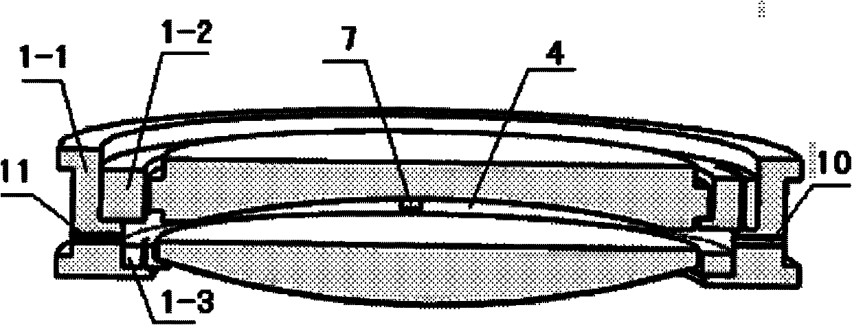
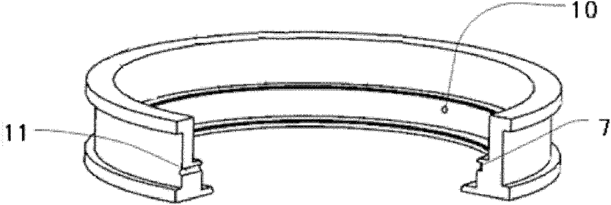
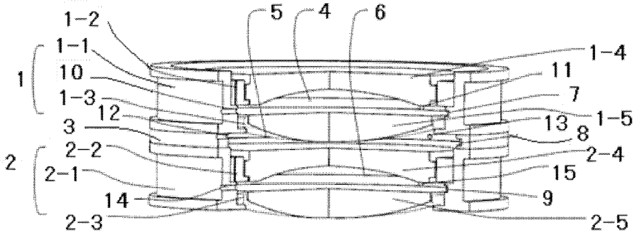
[0030] Specific implementation mode 1. Combination Figure 1 to Figure 8Describe this embodiment, the optical element gravity deformation air pressure difference compensation device in the projection objective lens system is characterized in that it includes a first lens barrel unit assembly 1, a second lens barrel unit assembly 2, a spacer ring 3, and a first gas pressure sensor 7 , a second gas pressure sensor 8 and a third gas pressure sensor 9; a spacer 3 is arranged between the first lens barrel unit assembly 1 and the second lens barrel unit assembly 2;

[0031] The first lens barrel unit assembly 1 includes a first lens barrel unit 1-1, a first lens frame unit 1-2, a second lens frame unit 1-3, a first optical element 1-4 and a second optical element 1-5 The first lens barrel unit 1-1 is a ring structure; the first lens frame unit 1-2 and the second lens frame unit 1-3 are sequentially installed in the first lens barrel unit 1-1; the first optical element 1 -4 and the ...

specific Embodiment approach 2

[0039] Specific implementation mode two, the present implementation mode is the method for the gravity deformation air pressure difference compensation of the optical element in the projection objective lens system, the concrete steps of this method are:

[0040] Step 1, the first gas pressure sensor 7, the second gas pressure sensor 8 and the third gas pressure sensor 9 measure the air pressure in the first sealed chamber 4, the second sealed chamber 5 and the third sealed chamber 6 respectively, and three The air pressure value in the sealed chamber is input to the main controller through the data acquisition card;

[0041] Step 2: The air pressure value obtained by the main controller according to step 1 is compared with the predetermined air pressure value; if each gas pressure sensor detects that the gas pressure value in the sealed cavity does not reach or exceed the predetermined air pressure value, then adjust the gas supply pipeline and exhaust In the working state of...


PUM

PropertyMeasurementUnit
Diameteraaaaaaaaaa

Abstract

The invention relates to an optical element gravity deformation draught head compensating device in projection objective system and a method thereof, solving the problems that the existing optical element gravity compensating device is difficult to mount and debug, manufacturing cost is high ad central region compensation of optical element can not be realized. The device comprises a first lens barrel unit assembly, a second lens barrel unit assembly, a space ring, a first gas pressure sensor, a second gas pressure sensor and a third gas pressure sensor; wherein the space ring is arranged between the first lens barrel unit assembly and the second lens barrel unit assembly. The method includes that the gas pressure sensor detects the pressure in a seal cavity, a signal is input to a main controller by virtue of a data acquisition card; the main controller adjusts the working states of a gas supply pipeline and an exhaust pipeline, and further optical element gravity compensation is realized. The invention is applicable to optical element gravity compensation of deep ultraviolet projective photoetching objective system.

Description

technical field [0001] The invention relates to a device and method for gravity compensation of an optical element, in particular to an optical element gravity compensation for a deep ultraviolet projection lithography objective lens system. Background technique [0002] Projection lithography equipment is the key equipment in the large-scale integrated circuit manufacturing process, and the projection lithography objective lens is the core component of the projection lithography device. Therefore, it is of great significance to ensure the optical performance of the projection lithography objective lens system. [0003] In recent years, with the continuous improvement of the line width of integrated circuits, the resolution of projection optical equipment has also gradually increased. At present, ArF excimer laser projection lithography equipment with a wavelength of 193.368nm has become the standard for integrated circuit manufacturing at 90nm, 65nm and 45nm nodes. mainstre...

Claims


Application Information

Patent Timeline
IPC IPC(8): G03F7/20G02B7/02
Inventor 赵磊巩岩张巍倪明阳王学亮袁文全
Owner CHANGCHUN INST OF OPTICS FINE MECHANICS & PHYSICS CHINESE ACAD OF SCI
Features
  • Generate Ideas
  • Intellectual Property
  • Life Sciences
  • Materials
  • Tech Scout
  • Unparalleled Data Quality
  • Higher Quality Content
  • 60% Fewer Hallucinations
Learn More