Tri-branch multi-frequency plane dipole antenna

A dipole antenna and three-branch technology, applied in the field of wireless communication, can solve the problems of difficulty in meeting the antenna requirements of 3G communication, high cost, poor shock resistance, etc.

Inactive Publication Date: 2010-12-08
SUZHOU WUTONG ANTENNA
View PDF4 Cites 2 Cited by
  • Summary
  • Abstract
  • Description
  • Claims
  • Application Information

AI Technical Summary

Problems solved by technology

However, it is known from its complex structure that it must have high cost and poor earthquake resistance
like image 3 It can be seen from the bandwi

Method used


Image

  • Tri-branch multi-frequency plane dipole antenna
  • Tri-branch multi-frequency plane dipole antenna
  • Tri-branch multi-frequency plane dipole antenna

Examples


Embodiment Construction

[0019] Aiming at the defects of antennas used in wireless communication in the field of existing communication technologies mentioned in the background technology, especially the antennas mainly for indoor coverage, the structure is complex, the volume is bulky, and the communication frequency supported is relatively narrow. , a three-branch multi-frequency planar dipole antenna that can fully support multi-standard communication such as 3G is proposed.

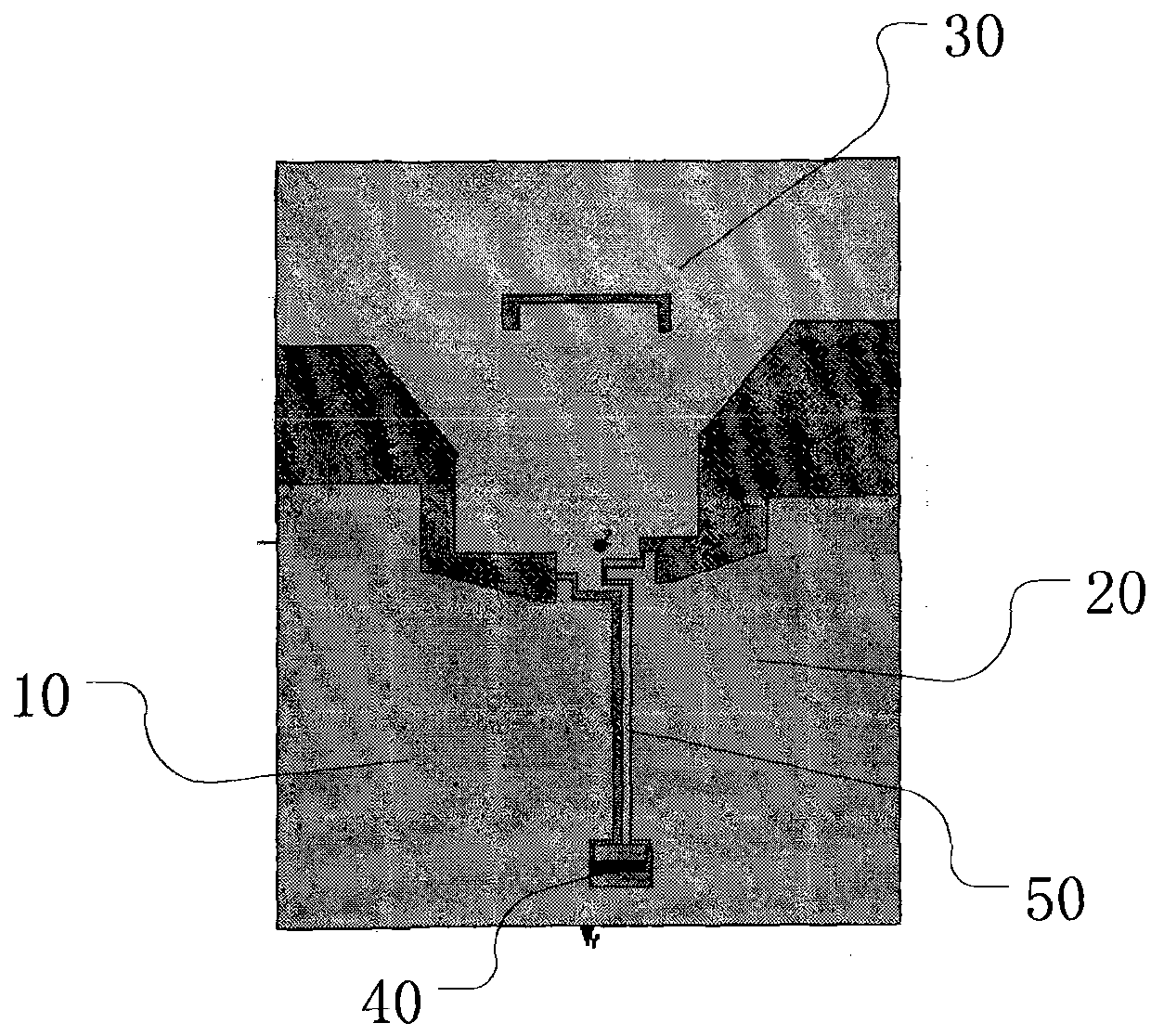
[0020] like figure 2 Shown is a schematic structural diagram of a preferred embodiment of the planar dipole antenna of the present invention. It can be seen from the figure that the three-branch multi-frequency planar dipole antenna includes a housing (not shown), a first branch 10, a second branch 20, a third branch 30, a copper exposed area 40 and a feed source 50, and the first branch 1. The second and third branches are respectively connected to corresponding circuits (the connected circuits are mature technologies well...


PUM


Abstract

The invention discloses a tri-branch multi-frequency plane dipole antenna, comprising a shell, a first branch, a second branch, a third branch, a copper exposure zone and a feed source, wherein the first branch, the second branch and the third branch are respectively connected with corresponding circuits. In particular, the first branch, the second branch and the third branch are laminated structures connected with each other in the same one plane, wherein the first branch and the second branch are symmetrically arranged at both sides of the third branch; the first branch and the second branch are jointly combined far away from one end of the third branch and are connected with the copper exposure zone at the lower end of a public area into a whole; the feed source is inserted between the first branch and the second branch and communicated with the third branch at the upper end of the copper exposure zone; and the third branch is a gradually widening structure back on to the copper exposure zone. The plane dipole antenna structure also has the advantages of small size, remarkable anti-vibration effect and excellent wireless communication performance; and therefore, the tri-branch multi-frequency plane dipole antenna can be widely applicable to 3G (The 3rd Generation Telecommunication) wireless terminal products of a CDMA2000 (Code Division Multiple Access 2000) system, a TD-SCDMA (Time Division-Synchronization Code Division Multiple Access) system, a WCDMA (Wideband Code Division Multiple Access) system, and the like.

Description

technical field [0001] The invention relates to a dipole antenna, in particular to a three-branch multi-frequency dipole antenna with a planar structure, belonging to the technical field of wireless communication. Background technique [0002] In the existing wireless communication technology, the traditional three-branch structure of the antenna is complex, and the insertion loss and anti-vibration effect are poor. It is difficult to meet the requirements of low cost, miniaturization, low insertion loss and high anti-vibration in the coming 3G era. [0003] like figure 1 The schematic diagram of the antenna structure in the prior art shown: it can be seen that the traditional antenna includes a housing (not shown), and the first branch 1, the second branch 2, the third branch 3, the exposed copper area 4 and the Feed 5. Wherein the first branch 1 is integrated with the exposed copper area 4, the second branch 2 is integrated with the feed source 5, and the first branch 1 ...

Claims


Application Information

Patent Timeline
IPC IPC(8): H01Q1/36H01Q5/00H01Q5/28
Inventor 康来利
Owner SUZHOU WUTONG ANTENNA
Why Eureka
Try Eureka