Method and system for generating through underground temperature difference
A technology of thermoelectric power generation and thermoelectric power generation module, which is applied in the directions of generators/motors, electrical components, etc., can solve problems such as low mud temperature, and achieve the effect of reducing the impact
- Summary
- Abstract
- Description
- Claims
- Application Information
AI Technical Summary
Problems solved by technology
Method used
Image

Examples
Embodiment Construction
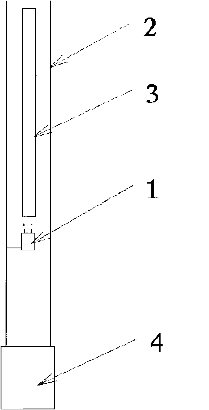
[0016] exist figure 1 In the shown embodiment, the thermoelectric power generation device (1) is installed in the drill stringer (2) with a heat insulation layer above the drill bit (4), and the wireless inclinometer while drilling (3) is located in the thermoelectric power generation device (1). above.
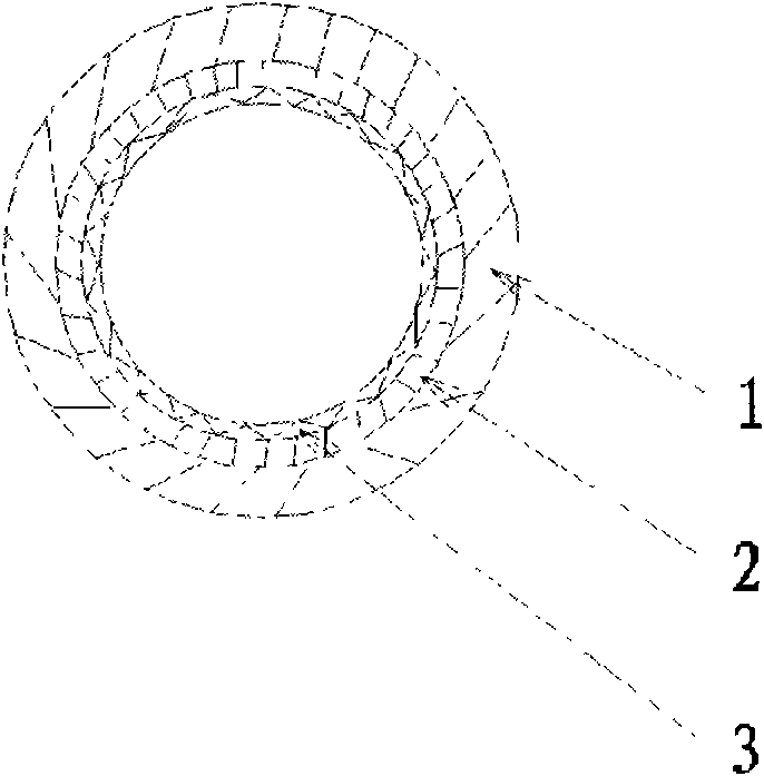
[0017] exist figure 2 In the shown embodiment, the inner wall layer (3) is fixed to the outer wall layer (1) from one end of the drill collar or drill pipe, and there is a uniform gap in the middle, and the liquid material forming polyurethane foam is poured into the gap, The heat insulation layer (2) is formed after foaming.
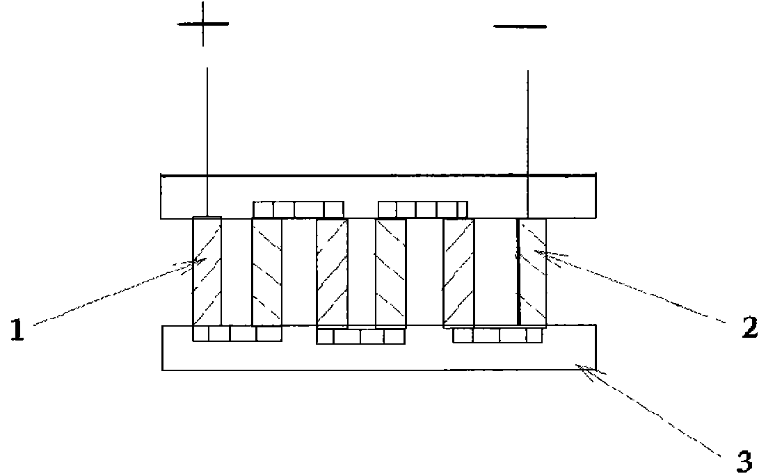
[0018] exist image 3 In the shown embodiment, two N-type semiconductors (1) and P-type semiconductors (2) are a power generation group, each group is connected to the bottom from left to right, and the second pin of the first group on the top part is connected to the second pin of the first group. The first pins of the second group are connected,...
PUM
 Abstract
Description
Claims
Application Information
PatSnap Eureka turns technology decisions into work you can execute. Powered by our Innovation Knowledge Graph, it runs expert workflows across engineering, life sciences, materials and intellectual property. Get your review-ready output in minutes.


