Downlink information transmission method and device of return link

A backhaul link and information transmission technology, which is applied in the field of downlink information transmission methods and equipment for backhaul links, can solve problems such as optimal design schemes for multiplexing of control areas and data areas on the backhaul link, and achieve the effect of ensuring compatibility

Inactive Publication Date: 2010-12-08
CHINA ACAD OF TELECOMM TECH
View PDF0 Cites 44 Cited by
  • Summary
  • Abstract
  • Description
  • Claims
  • Application Information

AI Technical Summary

Problems solved by technology

[0011] The present invention provides a backhaul link downlink information transmission method and equipment to solve the problem in t

Method used


Image

  • Downlink information transmission method and device of return link
  • Downlink information transmission method and device of return link
  • Downlink information transmission method and device of return link

Examples


Example Embodiment

[0101] Example one

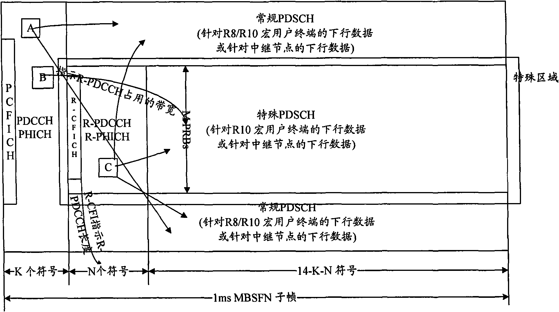
[0102] Picture 10 A schematic diagram of the FDM multiplexing design for the control and data areas of the backhaul link. As shown in the figure, if the R-PDCCH and R-PHICH areas are divided by FDM, the number of OFDM symbols occupied by the area in the time domain is N=14-K , The number of PRBs occupied in the frequency domain is M (1≤M Picture 10 As shown, the CCE resource mapping method specified by R8 can be used, or TDM, FDM, CDM, and hybrid methods can be used for resource mapping.

Example Embodiment

[0103] Example two

[0104] Picture 11 A schematic diagram of the TDM multiplexing design for the control and data areas of the backhaul link. As shown in the figure, if the R-PDCCH and R-PHICH areas are divided by TDM, the number of OFDM symbols occupied by the area in the time domain is N (1≤N Picture 11 As shown, mapping methods such as TDM, FDM, CDM, or hybrid methods can also be used.

Example Embodiment

[0105] Example three

[0106] Picture 12 Schematic diagram of the FDM+TDM multiplexing design for the control and data areas of the backhaul link. As shown in the figure, if the R-PDCCH and R-PHICH areas are divided by TDM+FDM, the number of OFDM symbols occupied by the area in the time domain is N (1≤N Picture 11 . In the implementation, the resource mapping of multiple RNs and R10UEs can follow the CCE-based resource mapping method specified by R8, such as Picture 12 As shown, mapping methods such as TDM, FDM, CDM, or hybrid methods can also be used.

[0107] In the implementation, in the implementation of step 802, before the relay node RN serves its subordinate user equipment R-UE, the eNB may use radio resource control RRC broadcast messages or dedicated high-level signaling for RN and / or R10UE to transfer the first area The resource configuration message is notified to the RN and / or R10UE.

[0108] Wherein, the first area resource configuration information transmitted by th...


PUM


Abstract

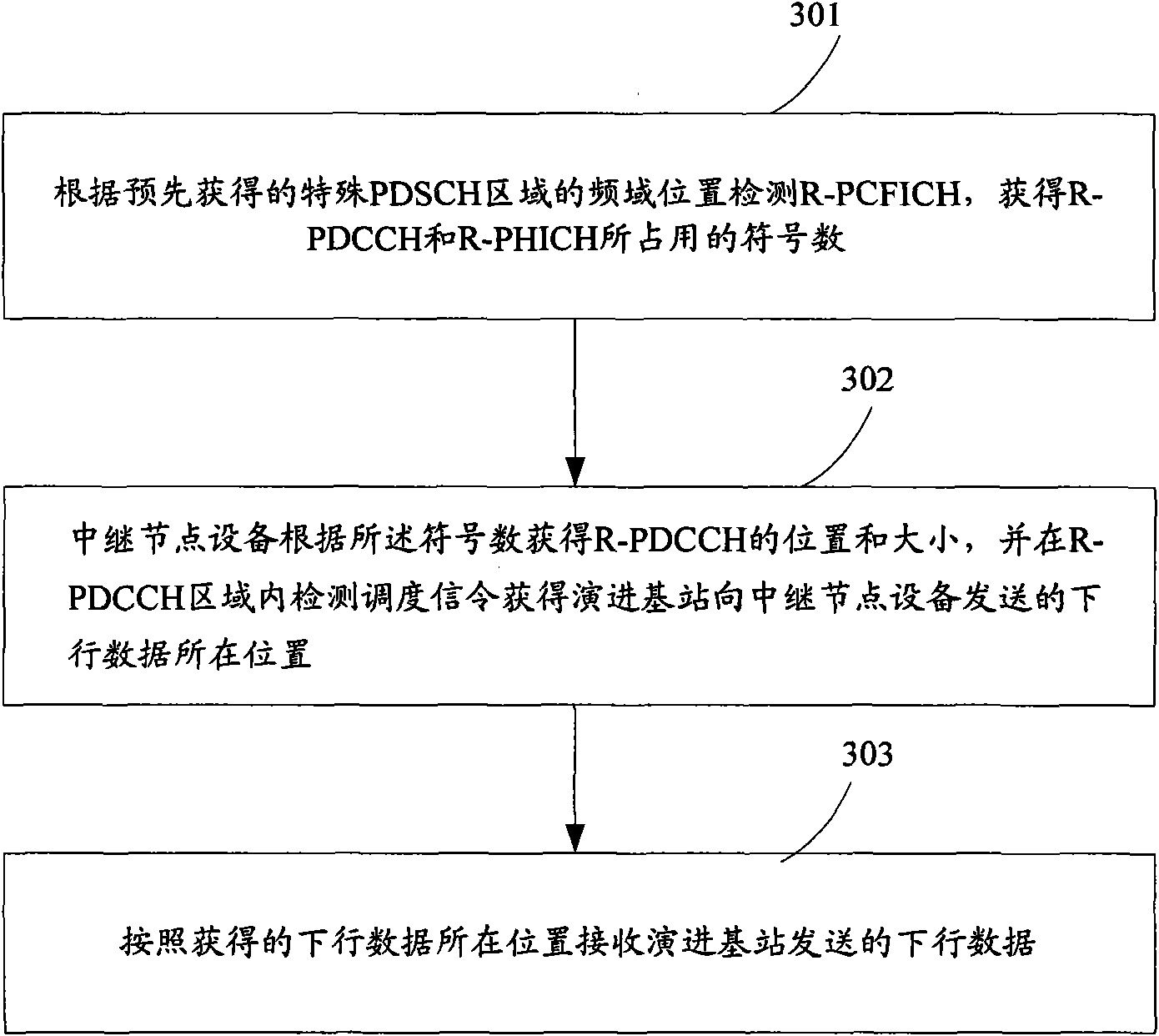
The invention discloses downlink information transmission method and device of a return link. The transmission method comprises the following steps of: determining a first area by an evolution base station, wherein the first area is used for transmitting downlink information to a relay node and/or a user device for supporting a 3GPP (The 3rd Generation Partnership Project) version 10 on the return link and comprises a relay physical downlink control channel area and a relay physical hybrid automatic repeat request (HARQ) indication channel area; notifying resource configuration information of the first area to the relay node and/or the user device for supporting the 3GPP version 10 through the evolution base station; and in the downlink return link, transmitting downlink information to the relay node and/or the user device for supporting the 3GPP version 10 in the first area through the evolution base station. The invention solves the problem that an LTE-A (Long Term Evolution-Advanced) system does not have an optimization design scheme related to control area and data area multiplexing on the return link, and provides a technical scheme which is used for a semi-static configuration control area of a downlink signal of the return link.

Description

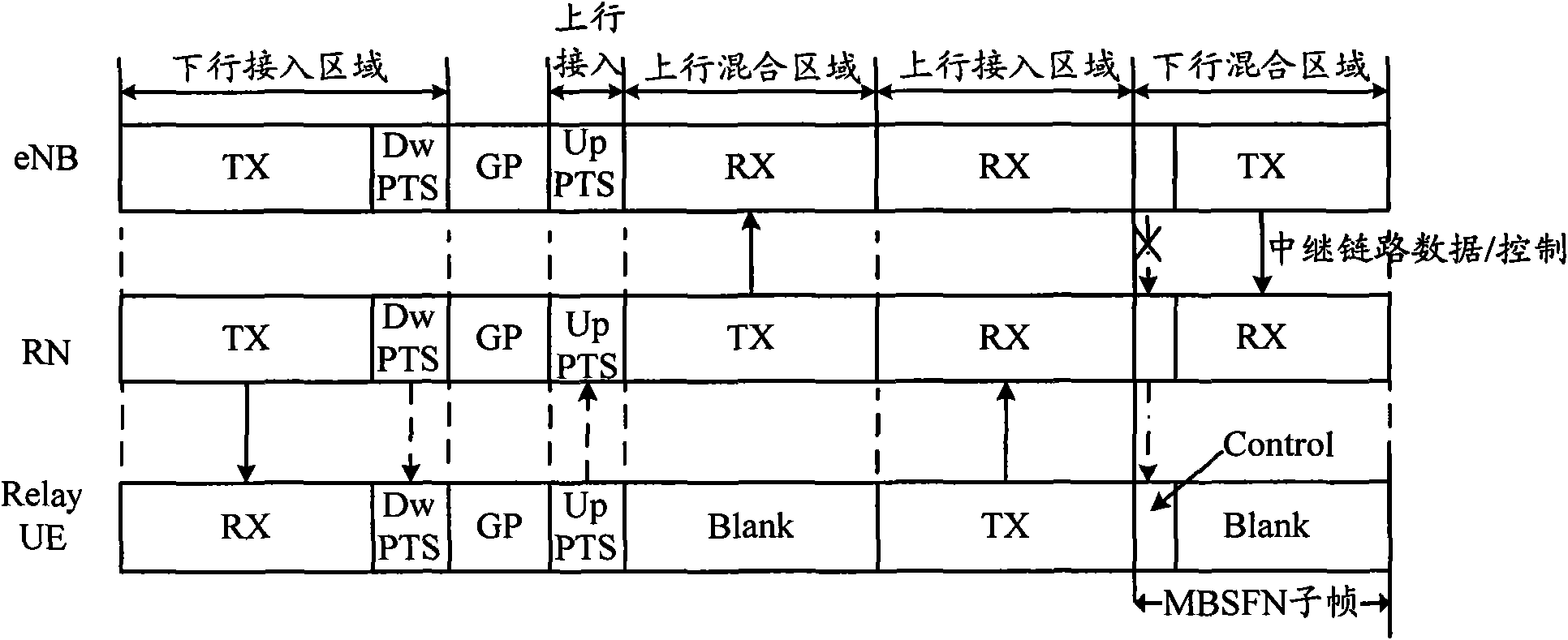
technical field [0001] The present invention relates to the field of communication technology, in particular to a backhaul link downlink information transmission method and equipment. Background technique [0002] In the 3GPP Advanced Long Term Evolution (LTE-Advanced, LTE-A) system, a relay (Relay) cooperative transmission method will be adopted to improve service quality of cell edge users and expand cell coverage. In the relay transmission of the LTE-A system, the frame structure can be divided into four areas: the downlink access area, the downlink mixed area, the uplink access area, and the uplink mixed area. see figure 1 As shown, in the downlink access area, the evolved base station (eNB) and the relay node device (RN) send data to the macro user terminal (Macro UE) and the relay user equipment (Relay UE) respectively; in the downlink hybrid area, the eNB Send data to RN and Macro UE; in the uplink access area, Macro UE and Relay UE send data to eNB and RN respectiv...

Claims


Application Information

Patent Timeline
IPC IPC(8): H04L1/18H04L1/16H04W72/04H04W72/14H04W88/08
CPCH04W28/06H04W16/12
Inventor 张文健潘学明沈祖康肖国军王立波
Owner CHINA ACAD OF TELECOMM TECH
Why Eureka
Try Eureka