Printed circuit board

A printed circuit board, cross-slot technology, applied in the direction of printed circuit, printed circuit, printed circuit components, etc., can solve the problem of increasing the cost of printed circuit boards

Inactive Publication Date: 2010-12-08
HONG FU JIN PRECISION IND (SHENZHEN) CO LTD +1
View PDF1 Cites 8 Cited by
  • Summary
  • Abstract
  • Description
  • Claims
  • Application Information

AI Technical Summary

Problems solved by technology

However, limited by the limitations of actual wiring, not all occasions are suitable for connecting capacitors. In addition, adding capacitors also increases the cost of printed circuit boards

Method used


Image

  • Printed circuit board
  • Printed circuit board
  • Printed circuit board

Examples


Embodiment Construction

[0009] The present invention will be further described in detail below in conjunction with the accompanying drawings and preferred embodiments.

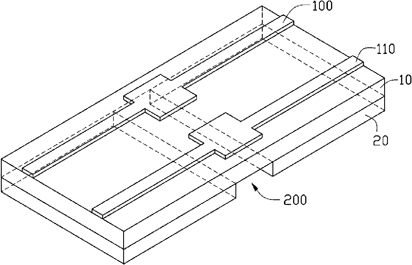
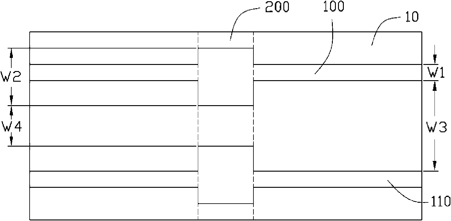
[0010] Please refer to figure 1 and 2 , the preferred embodiment of the printed circuit board of the present invention includes a first layer 10 and a second layer 20 .

[0011] A differential pair including two differential signal lines 100 and 110 is disposed on the first layer 10 . A span groove 200 is disposed on the second layer 20 . When the printed circuit board has fewer layers, different voltage levels need to be cut on the limited power layer, and the cross-slot 200 is formed when the signal line crosses these different voltage cutting planes.

[0012] The line width of the differential signal line 100 above the non-spanning trench 200 is W1, and the line width above the spanning trench 200 is W2, wherein W1 is smaller than W2. The setting of the line width of the differential signal line 110 is the same as that of the ...


PUM


Abstract

The invention discloses a printed circuit board. The printed circuit board comprises a first layer and a second layer, wherein the first layer is provided with a pair of differential signal lines; the second layer comprises a cross groove; with respect to the two differential signal lines, the widths of the portions which are not positioned above the cross groove are less than those of the portions which are positioned above the cross groove; and with respect to the two differential signal lines, the space between the portions which are not positioned above the cross groove are greater than that between the portions which are positioned above the cross groove. The printed circuit board avoids the discontinuity of impedance by increasing the line widths of the portions of the differential signal lines positioned above the cross groove, so the signal transmission capacity of the differential signal lines positioned above the cross groove can be improved well.

Description

technical field [0001] The invention relates to a printed circuit board. Background technique [0002] Based on the consideration of product price, the current printed circuit board needs to use as few layers as possible when designing. When using fewer layers, different voltage levels must be cut on the limited power planes, so that if the transmission line crosses these different voltage cut planes, a cross-slot is formed. These cross-slots are the main factors leading to the phenomenon of electromagnetic interference. The current known method is to use a capacitor to connect the two ends of the cross-slot to provide a current return bridge for the two different voltage cutting planes, so as to minimize the loop area formed during signal transmission and return, which can reduce Small electromagnetic interference phenomenon. However, limited by actual wiring, not all occasions are suitable for connecting capacitors. In addition, adding capacitors also increases the cost...

Claims


Application Information

Patent Timeline
Patent Type & Authority Applications(China)
IPC IPC(8): H05K1/00H05K1/02H05K1/11
CPCH05K1/0216H05K2201/09663H05K2201/09727H05K2201/093H05K1/0245H05K1/0227H05K1/0262
Inventor 陈永杰刘建宏许寿国
Owner HONG FU JIN PRECISION IND (SHENZHEN) CO LTD
Why Eureka
Try Eureka