Liquid crystal display device
A liquid crystal display device, laser technology, applied in lighting devices, optics, light sources, etc., can solve the problems of low utilization efficiency, limited improvement of light utilization efficiency, waste of light, etc., and achieve the effect of simple brightness
- Summary
- Abstract
- Description
- Claims
- Application Information
AI Technical Summary
Problems solved by technology
Method used
Image
Examples
no. 1 approach
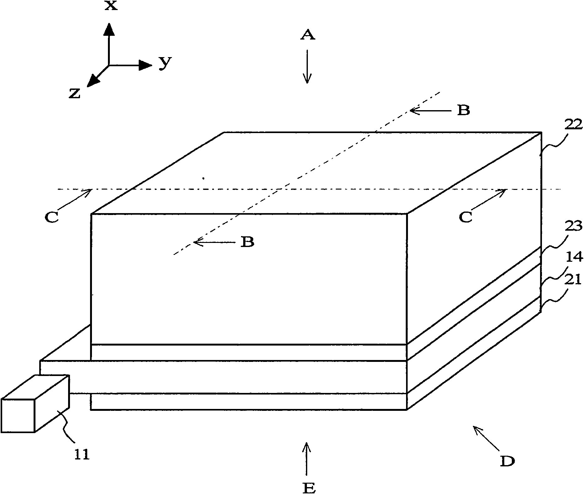
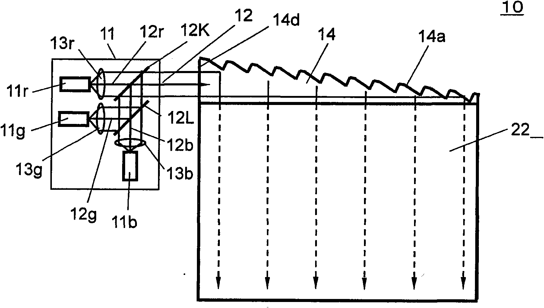
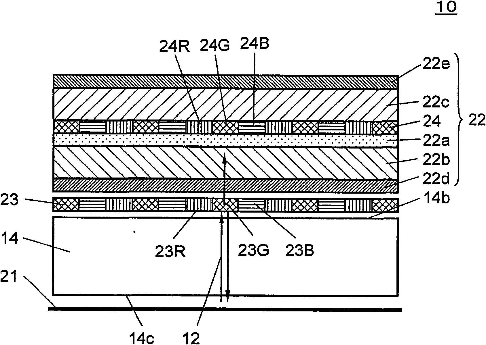
[0073] Figure 2A ~ Figure 2C It is a diagram illustrating the configuration of the liquid crystal display device 10 according to the first embodiment of the present invention. Figure 2A From figure 1 The sagittal graph seen at point A in, Figure 2B yes figure 1 The vertical section of the B-B line in the XZ plane, Figure 2C yes figure 1 The vertical section of the middle C-C line on the XY plane. in addition, Figure 2A The laser light 12 (dotted arrow) transmitted through the liquid crystal panel 22 and propagating in the light guide plate 14 is depicted in .
[0074] Figure 2A Among them, the laser light source unit 11 includes: a red laser light source 11r, a green laser light source 11g, a blue laser light source 11b, collimator lenses 13r, 13g, and 13b, and dichroic mirrors 12K and 12L. The red laser light source 11r emits red laser light, the green laser light source 11g emits green laser light, and the blue laser light source 11b emits blue laser light. Th...
no. 2 approach
[0099] Figure 9A and 9B It is a figure explaining the structure of the liquid crystal display device 20 which concerns on 2nd Embodiment of this invention. Figure 9A From figure 1 The sagittal graph seen at point A in, Figure 9B yes figure 1 The vertical section of the B-B line in the XZ plane, Figure 9C yes figure 1 The vertical profile of line C-C in XY plane. in addition, Figure 9A is depicted to be able to understand the laser light 12 passing through the liquid crystal panel 22 and propagating in the light guide plate 14 (dotted arrow).
[0100] The liquid crystal display device 20 according to the second embodiment is different from the liquid crystal display device 10 according to the above-mentioned first embodiment in the light guide plate 31 and the wavelength selection substrate 33 , and the other configurations are the same. The liquid crystal display device 20 will be described below regarding this difference.
[0101] The structure of the light guid...
no. 3 approach
[0110] Figure 10A and Figure 10B It is a figure explaining the structure of the liquid crystal display device 30 which concerns on 3rd Embodiment of this invention. Figure 10A From figure 1 The sagittal graph seen at point A in, Figure 10B yes figure 1 The vertical profile of the B-B line in the XZ plane. in addition, Figure 10A is depicted to be able to understand the laser light 12 transmitted through the liquid crystal panel 32 and propagating in the light guide plate 14 (dotted arrow).
[0111] The liquid crystal display device 30 according to the third embodiment is different from the liquid crystal display device 10 according to the above-mentioned first embodiment in the structure of the wavelength selection substrate 23 and the liquid crystal panel 32 , and the other structures are the same. The liquid crystal display device 30 will be described below regarding this difference.
[0112] The liquid crystal panel 32 includes a liquid crystal layer 22a, a wave...
PUM
| Property | Measurement | Unit |
|---|---|---|
| width | aaaaa | aaaaa |
| thickness | aaaaa | aaaaa |
| thickness | aaaaa | aaaaa |
Abstract
Description
Claims
Application Information
 - R&D
- Intellectual Property
- Life Sciences
- Materials
- Tech Scout
- Unparalleled Data Quality
- Higher Quality Content
- 60% Fewer Hallucinations
Browse by: Latest US Patents, China's latest patents, Technical Efficacy Thesaurus, Application Domain, Technology Topic, Popular Technical Reports.
© 2025 PatSnap. All rights reserved.Legal|Privacy policy|Modern Slavery Act Transparency Statement|Sitemap|About US| Contact US: help@patsnap.com


