Etching method of metal micro-holes

An etching and micro-hole technology, used in metal processing equipment, laser welding equipment, manufacturing tools, etc., can solve the problems of application limitations, excessive fronts, and large equipment investment, so as to reduce the loss of resources, expand the scope of application, and improve the The effect of machining accuracy

Inactive Publication Date: 2010-12-15
叶淦波
View PDF1 Cites 21 Cited by
  • Summary
  • Abstract
  • Description
  • Claims
  • Application Information

AI Technical Summary

Problems solved by technology

[0002] At present, three methods are used to form holes: CNC machine tools, laser perforation and chemical etching. All three methods have application limitations.
The advantage of CNC machine tool hole forming is high machining accuracy, but the disadvantage is that the equipment investment is large, micro holes with a diameter of less than -0.5 cannot be processed, and there are many ridges after processing, which is troublesome to deal with, and it is difficult to form holes on 3D curved surfaces; The advantage of laser drilling is that the drilling speed is fast, and any 3D curved surface can be penetrated to form a hole. The disadvantage is that the hole is trumpet-shaped, and there is a sharp edge after the hole is formed; the advantage of chemical etching is less investment and high production efficiency. High, no edge after forming holes; the disadvantage is that for stainless steel plates with a thickness of more than 0.4mm, it is difficult to produce micro-holes, and the hole-forming effect is not ideal

Method used


Image

  • Etching method of metal micro-holes
  • Etching method of metal micro-holes
  • Etching method of metal micro-holes

Examples


Embodiment Construction

[0027] The present invention will be described in further detail below in conjunction with accompanying drawing and embodiment:

[0028] see figure 1 As shown, the metal micropore etching method includes the following processing steps:

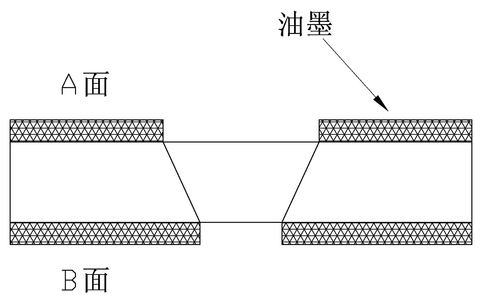
[0029] Process 1, oil spraying, uniformly spray a layer of black photosensitive ink layer on the metal workpiece, the thickness of the oil spraying is the minimum requirement that the ink layer does not fall off after laser perforation;

[0030] Process 2, laser laser perforation, using laser to perforate the metal workpiece, the perforation aperture is smaller than the final forming aperture; the laser energy is subject to not destroying the ink coating,

[0031] Since the laser drilling is trumpet-shaped, it cannot be formed according to the required aperture diameter. The purpose of the laser laser is to perforate, and then the subsequent chemical etching is used to correct the aperture requirement;

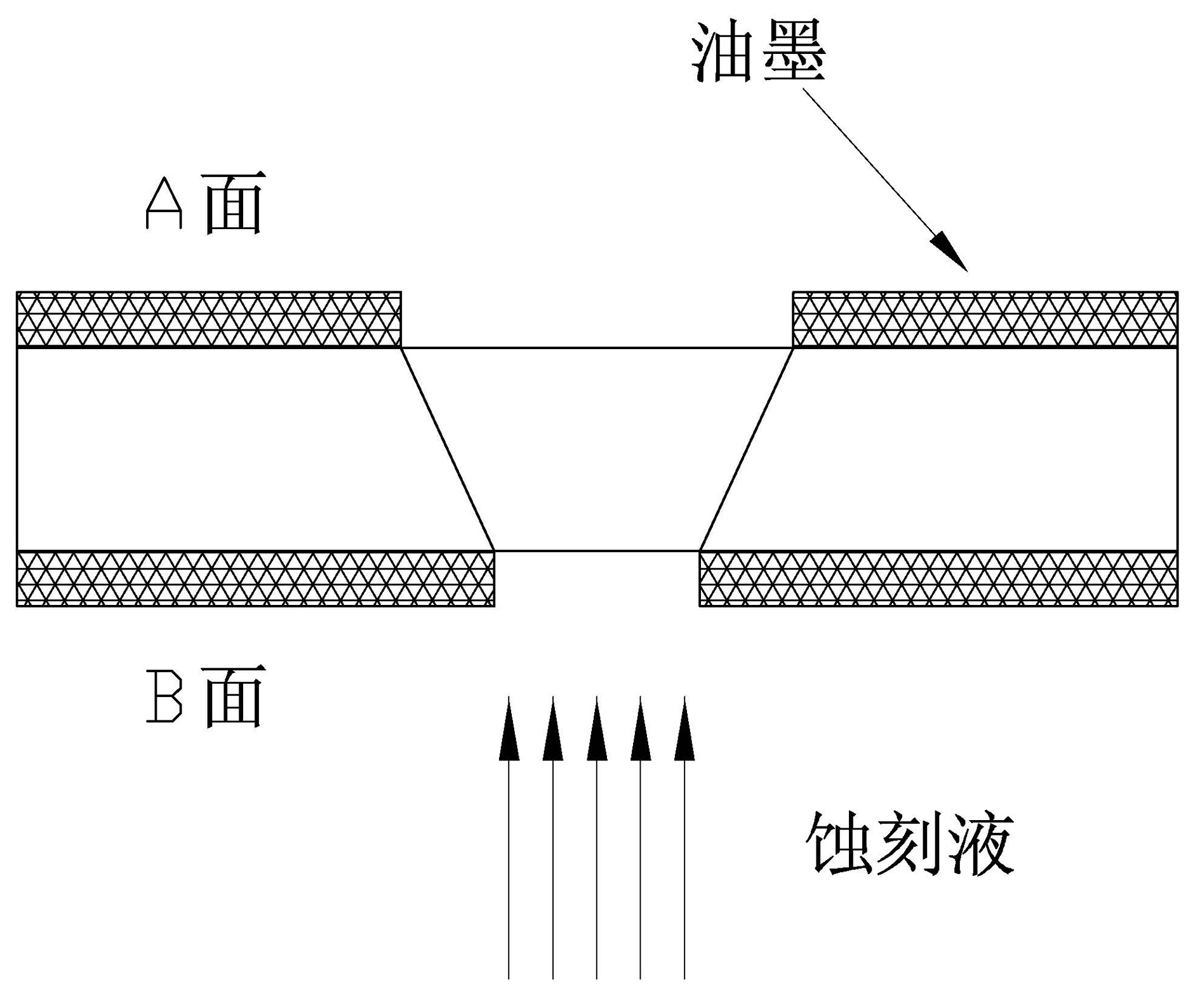
[0032] Step 3, chemical etching, uses...


PUM

PropertyMeasurementUnit
thicknessaaaaaaaaaa
diameteraaaaaaaaaa
diameteraaaaaaaaaa

Abstract

The invention relates to an etching method of metal micro-holes, which comprises the following processing process steps: process step 1) spraying oil: uniformly spraying an ink layer on a metal workpiece, and leading the thickness of sprayed oil to meet the minimum requirement of avoiding the ink layer after laser perforation from shedding; process step 2) laser perforation: using laser to perforate on the metal workpiece, and leading the perforated hole diameter to be smaller than the finally formed hole diameter; and meeting the requirement of avoiding the laser energy from damaging an ink coating; and process step 3) chemical etching: using etching solution to respectively carry out etching by times from two sides of the workpiece, and leading the diameters at two ends of the hole to meet the finally formed hole diameter. The etching method of the metal micro-holes can process the micro-holes with the diameter of 0.2mm-0.5mm of 3D curved surfaces and stainless steel sheets with the thickness of 0.4mm-1.0mm which can not be processed by the traditional process, and eliminate burrs during the processing process.

Description

technical field [0001] The invention relates to a metal micropore etching method. Background technique [0002] At present, three methods are used for hole forming: CNC machine tool, laser perforation and chemical etching. All three methods have application limitations. The advantage of CNC machine tool hole forming is high machining accuracy, but the disadvantage is that the equipment investment is large, micro holes with a diameter of less than -0.5 cannot be processed, and there are many ridges after processing, which is troublesome to deal with, and it is difficult to form holes on 3D curved surfaces; The advantage of laser drilling is that the drilling speed is fast, and any 3D curved surface can be penetrated to form a hole. The disadvantage is that the hole is trumpet-shaped, and there is a sharp edge after the hole is formed; the advantage of chemical etching is less investment and high production efficiency. High, no edge after hole formation; the disadvantage is t...

Claims


Application Information

Patent Timeline
Patent Type & Authority Applications(China)
IPC IPC(8): B23P15/00B23H9/14B23K26/36B23K26/362
Inventor 叶淦波
Owner 叶淦波
Why Eureka
Try Eureka