
Extrusion forming equipment and method for laminating flexible material

A flexible material, extrusion molding technology, applied in chemical instruments and methods, lamination, lamination devices, etc., can solve the problems of not being subjected to pressure, warping, and large pressure tools, and achieve the effect of avoiding warping

Inactive Publication Date: 2010-12-15
大卫·毕博
View PDF6 Cites 5 Cited by
  • Summary
  • Abstract
  • Description
  • Claims
  • Application Information

AI Technical Summary

Problems solved by technology

There are several drawbacks to this approach: 1) The force applied to the layer is applied along a single axis only, which is fine for layers where all surfaces are perpendicular to the pressure axis, however, if any surface parallel to the pressure axis, then the surfaces will not be stressed enough to hold them together
2) In order to maintain the stiffness of the entire tool surface, the pressure tool used in this method needs to be very large, which results in a large thermal mass of the pressure tool and takes a considerable time to heat and cool
This, in turn, requires separate tools for heating and cooling. The formed object needs to be extruded in the heated tool, then removed from the heated tool and transferred to the cooled tool. Even if the transfer period is brief, the formed object is not constrained, which will cause it to experience unevenness. Warps when cooled

Method used


Image

  • Extrusion forming equipment and method for laminating flexible material
  • Extrusion forming equipment and method for laminating flexible material
  • Extrusion forming equipment and method for laminating flexible material

Examples


Embodiment Construction

[0046] The features and advantages of the present invention will be described in detail with reference to the accompanying drawings.

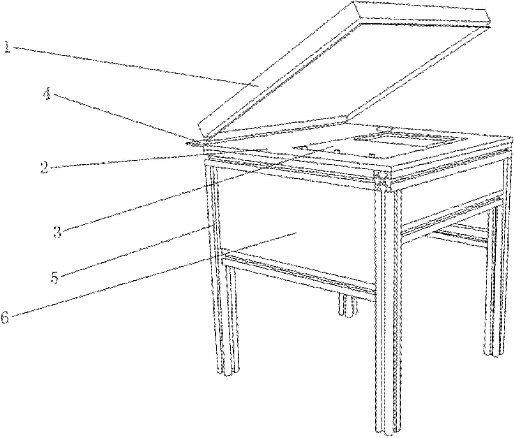
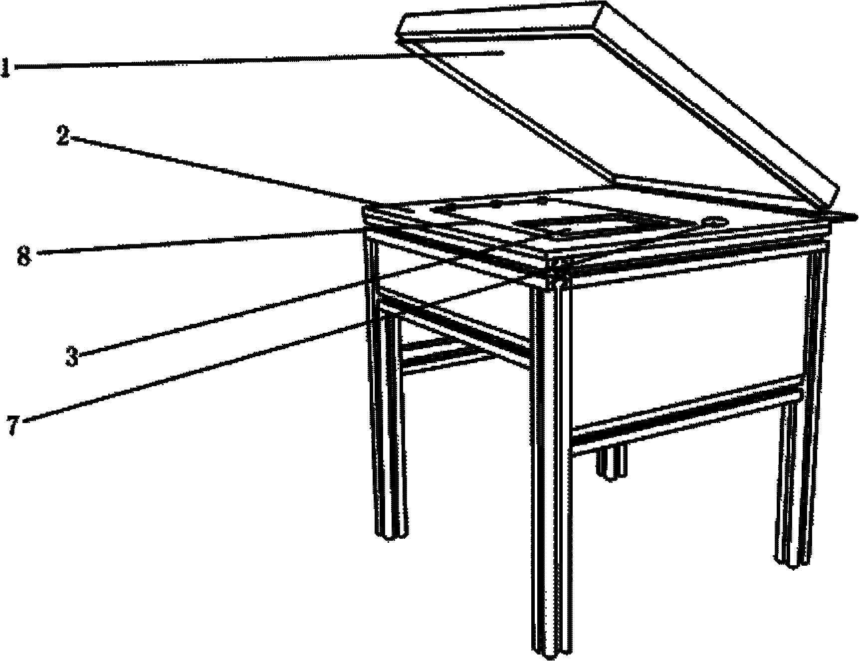
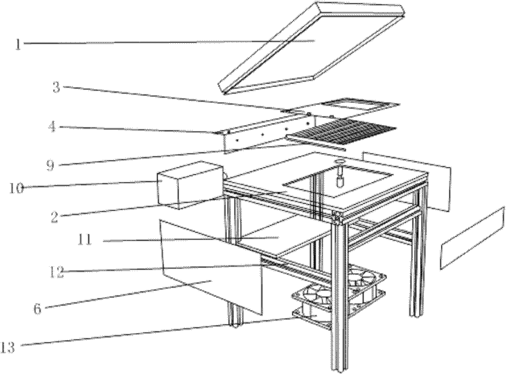
[0047] Please refer to Figure 1 to Figure 8, the extrusion molding equipment of the present invention comprises following main parts: pressure member 1, forming mold (Mandrel) 3, vacuum press (Thin-Air Vacuum Press, TAVP), heating device, cooling device (not shown) and control system (not shown). The forming die 3 is thermally conductive and has recesses for receiving the layer of flexible material and determining the three-dimensional shape of the product to be formed. The pressure member 1 has elasticity and heat resistance, and is configured to cover the forming mold 3 to form an airtight chamber surrounding the material layer. A vacuum press is coupled to the airtight chamber, which deforms the elastic covering surface of the pressure piece 1 tending to conform to the shape of the recess by vacuum suction to compress the material layer. ...


PUM


Abstract

The invention discloses extrusion forming equipment for laminating a flexible material. The equipment comprises a forming die with heat conductivity, a pressure member with elasticity and heat resistance, a vacuum press, a heating device, a cooling device and a control system, wherein the forming die is provide with a concave part for accommodating the flexible material layer and determining the three-dimensional shape of a product to be formed; an air-tight chamber enclosing the material layer can be formed by covering the pressure member on the forming die; the vacuum press is coupled to the air-tight chamber and used for making the coverage area of the pressure member tend to conform to the deformation of the concave part under the vacuum draw action so as to extrude the material layer; the heating device is thermally coupled to the forming die and used for heating the forming die; the cooling device is thermally coupled to the forming die and used for cooling the forming die; and the control system is used for controlling the operation of the vacuum press, the heating device and the cooling device. Through the equipment and the method, the coverage area of the pressure member tends to conform to the deformation of the concave part under the vacuum draw action so as to extrude the material layer, and the material layer is heated at the same time, so that a three-dimensional shape of the material layer taking the forming die as a substrate is obtained.

Description

technical field [0001] The present invention relates to material forming, and in particular to an extrusion forming apparatus for laminating flexible composite materials such as fabric, leather, etc. into semi-rigid three-dimensional shapes. Background technique [0002] When forming laminates containing flexible materials, the ideal laminate should consist of only the base material without additional ribs and skeletons that are commonly used in existing manufacturing processes to The desired shape is maintained while reducing the thickness of the layer. Take the example of forming a shoe made of leather and fabric. In the shoe industry, the outermost leather layer of the shoe is laminated to the inner layer using hot melt material, usually thick. These hot melt materials contain woven meshes within a polymer matrix that provide the basic shape backbone. In this process, the layers are pressed together by a pneumatic press on a single pressure axis. There are several draw...

Claims


Application Information

Patent Timeline
IPC IPC(8): B32B37/06B32B37/10
Inventor 大卫·毕博
Owner 大卫·毕博
Learn More