Uniwafer three-disk magnetic rheological clutch

A magnetorheological and clutch technology, applied in fluid clutches, clutches, mechanical equipment, etc., can solve the problems of large clutch volume, inconvenient processing-installation-disassembly, complex structure design, etc., and achieve the effect of small size

Inactive Publication Date: 2010-12-15
HOHAI UNIV
View PDF13 Cites 13 Cited by
  • Summary
  • Abstract
  • Description
  • Claims
  • Application Information

AI Technical Summary

Problems solved by technology

[0005] Many scientific research departments and research institutions have explored and researched magnetorheological clutches. Foreign magnetorheological clutch patents include: US patents US005,845,753A, US005,823,309A, US005,845,752A, European patents EP0776813A1 and EP0879973; Patents: "radial self-pressurized magnetorheological fluid clutch" disclosed in CN00104451.6, "magnetorheological stepless transmission" disclosed in CN03135802.0, "rotary magnetorheological brake" disclosed in CN200410084576.7, CN01137376.6 The disclosed "centrifugal magneto-rheological fluid clutches" etc. overcome the shortcomings of traditional clutches. Torque is generally adopted by increasing the number of blades, reducing the working gap, and applying pressure to the magneto-rheological fluid. The clutches of these designs have the problems of large volume, complex structural design, and inconvenient processing-installation-disassembly.

Method used


Image

  • Uniwafer three-disk magnetic rheological clutch
  • Uniwafer three-disk magnetic rheological clutch
  • Uniwafer three-disk magnetic rheological clutch

Examples


Embodiment Construction

[0027] The present invention will be further described in detail below in conjunction with the drawings.

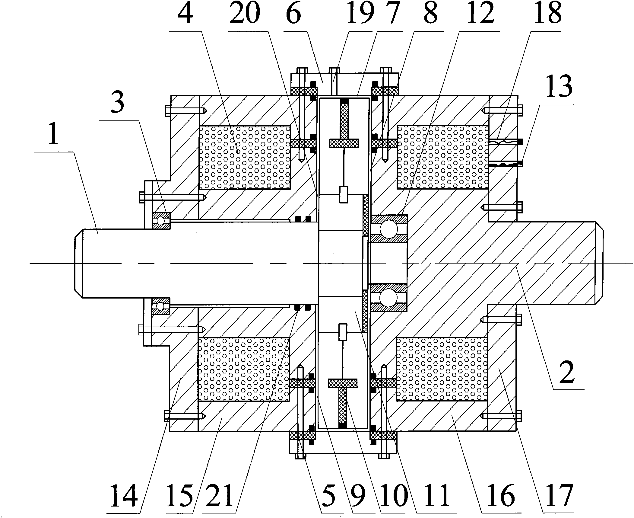
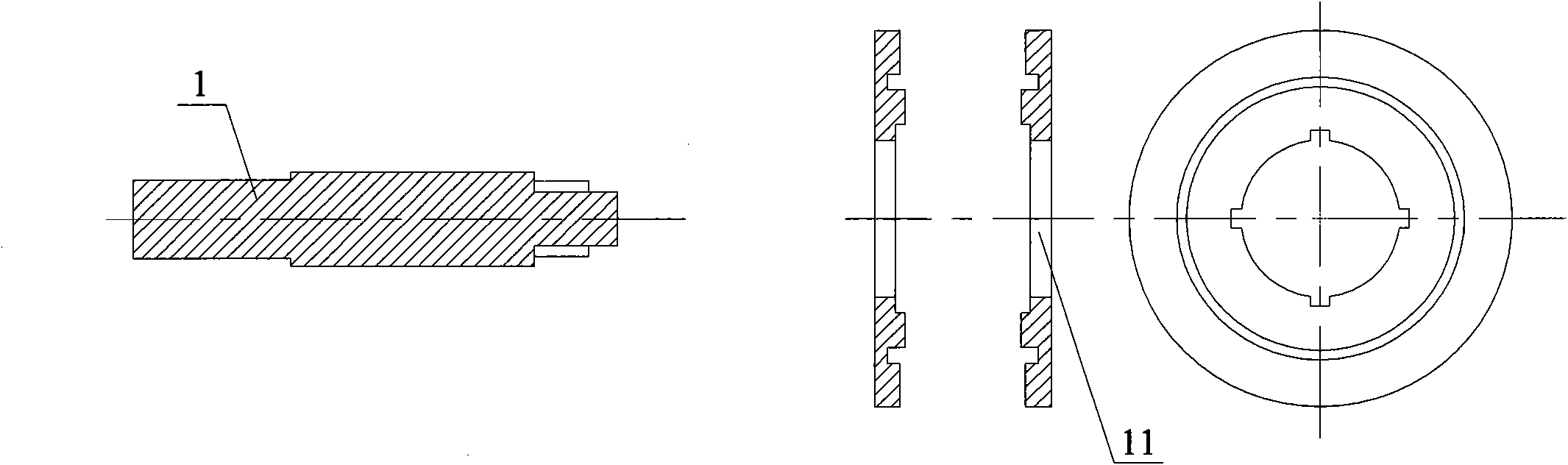
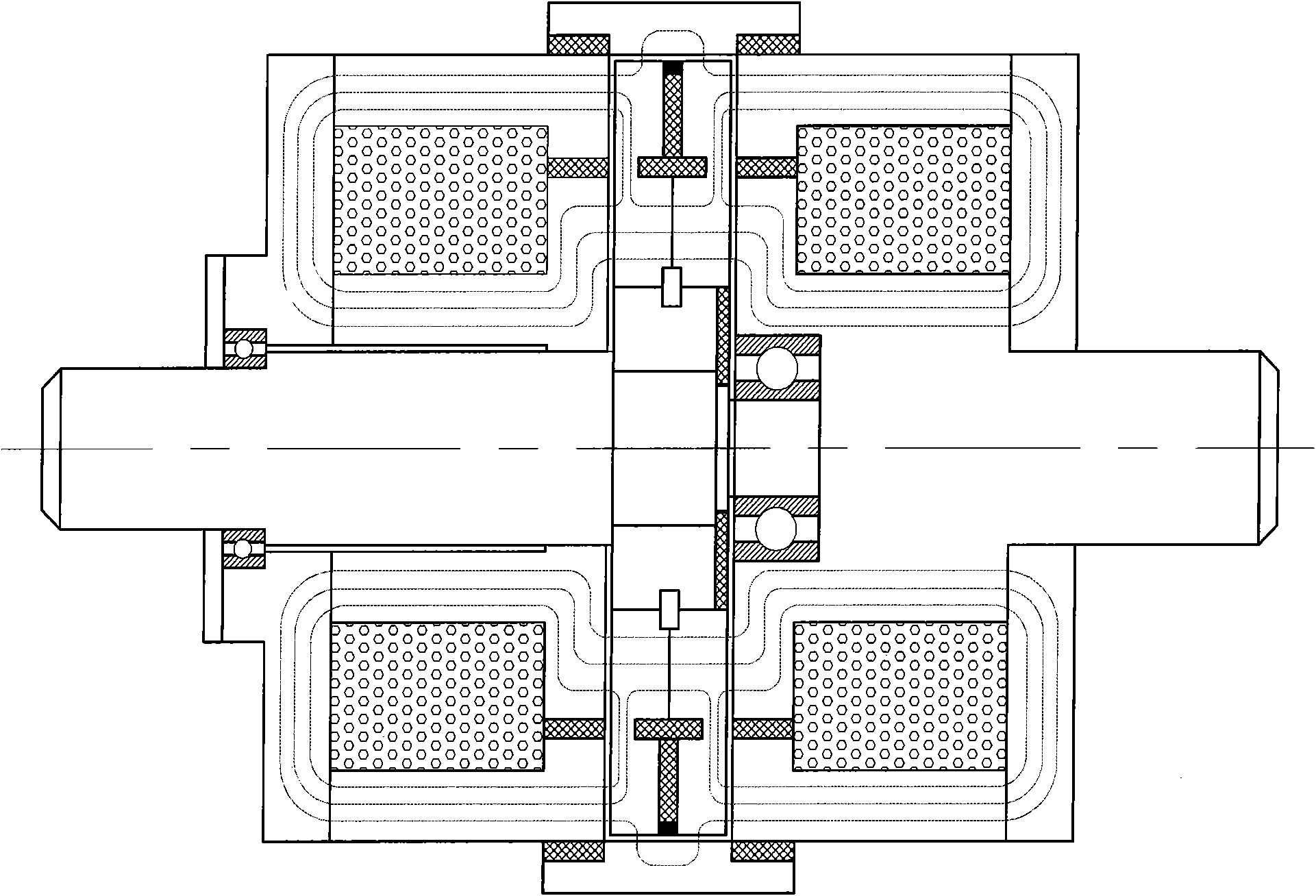
[0028] Such as figure 1 A single-plate three-disc magnetorheological clutch is shown, which includes a driving shaft (1), a driven shaft (2), a driving disc (11), an excitation coil (4), and a magnetorheological left disc channel (9) ), magnetorheological right disc channel (8), magnetorheological ring channel (7), left casing (14), left follower (15), right casing (17), right follower ( 16) Active disc magnetic isolation copper ring (10), follower magnetic isolation copper ring (5), angular contact ball bearing (3), thrust ball bearing (12), magnetorheological fluid (20) and sealing device, It is characterized in that: the driving shaft (1), the driving disk (11), and the driving disk magnetic isolation copper ring (10) are combined into the driving body. The structure of the driving shaft (1) and the driving disk (11) is as follows figure 2 As shown; the driving shaft (...


PUM


Abstract

The invention discloses a uniwafer three-disk magnetic rheological clutch which comprises a drive shaft (1), a driven shaft (2), a drive disk (11), a magnet exciting coil (4), a magneto rheological left disk channel (9), a magneto rheological right disk channel (8), a magneto rheological circular channel (7), a left shell (14), a left driven member (15), a right shell (17), a right driven member (16), a drive disk magnetism-isolating copper ring (10), a driven member magnetism-isolating copper ring (5), an angle contact ball bearing (3), a thrust ball bearing (12), a magneto rheological liquid (20) and a sealing device, wherein the drive disk (11) is positioned in a cavity surrounded by the left driven member (15), the right driven member (16) and a driven connecting member (6), and the magneto rheological liquid is filled in the cavity; and magnetic fields vertical to three disk surfaces of the drive disk (11) pass through the same, which can more effectively develop magneto rheological effect. The invention overcomes the defects of slow response, easy abrasion, large noise, more heat generation, unstable control and the like of the traditional clutch, and has the advantages of smaller volume, bigger drive torque, simpler structural design and less power consumption compared with the traditional magneto rheological clutch.

Description

Technical field [0001] The present invention mainly relates to a transmission mechanical device, in particular to a clutch device that uses magnetorheological fluid to generate transmission torque. Background technique [0002] The clutch is a device that connects the main and driven parts to transmit power or movement. It can ensure a smooth start of the car; realize smooth shifting during driving; and prevent the drive train from overloading when the car is braked urgently. Traditional clutches generally have friction clutches, hydraulic torque converters (hydraulic couplings), electromagnetic clutches and other forms. Among them, friction clutches are divided into wet and dry types. In the operation of traditional clutch vehicles, there are faults such as slippage, poor separation, shaking at start, abnormal noise and heavy pedals. More than 50% of these faults are caused by clutch wear, and the wear of the clutch friction plate is the main cause, which seriously affects the s...

Claims


Application Information

Patent Timeline
Patent Type & Authority Applications(China)
IPC IPC(8): F16D37/02
Inventor 于国军杜成斌戴上秋雷冬
Owner HOHAI UNIV
Why Eureka
Try Eureka