
Method and device for double-star time difference/frequency difference combined positioning

A joint positioning and time difference technology, applied in satellite radio beacon positioning systems, measuring devices, instruments, etc., can solve the problems of shortening the calculation time of fuzzy functions, complex equipment, and low positioning accuracy, and achieve fast operation speed, measurement accuracy and The effect of high positioning accuracy and high positioning accuracy

Active Publication Date: 2013-10-30
10TH RES INST OF CETC
View PDF6 Cites 0 Cited by
  • Summary
  • Abstract
  • Description
  • Claims
  • Application Information

AI Technical Summary

Problems solved by technology

[0021] In order to overcome the defects of low positioning accuracy of direction finding cross positioning and complex equipment for three-station time difference positioning, improve positioning accuracy, reduce the complexity of positioning equipment, and reduce the power consumption of positioning equipment, the present invention proposes a high positioning accuracy, A dual-satellite time-difference / frequency-difference joint positioning method and device with large coverage area, good real-time performance, practicality and speed, and can effectively shorten the calculation time of ambiguity functions

Method used


Image

  • Method and device for double-star time difference/frequency difference combined positioning
  • Method and device for double-star time difference/frequency difference combined positioning
  • Method and device for double-star time difference/frequency difference combined positioning

Examples


Embodiment Construction

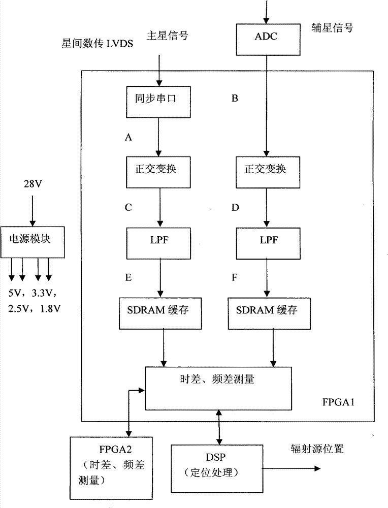
[0041] figure 1 The schematic diagram of the dual satellite time difference and frequency difference joint positioning method is described. exist figure 1 In this method, the specific implementation steps are as follows: (1) use the superheterodyne receiver to receive the radio frequency signals received on the main star and the auxiliary star, and change them to a certain intermediate frequency to obtain the intermediate frequency signals A and B; (2) use the module The digital converter samples the A and B received on the main star and the auxiliary star to obtain C and D; (3) uses a digital down-converter to perform orthogonal transformation on C and D to obtain E and F; (4) uses a digital The filter performs low-pass filtering on E and F to obtain G and H; (5) Use the following method to measure time difference and frequency difference in FPGA to obtain time difference and frequency difference I and J.

[0042] Aiming at the special application environment where the Dopp...


PUM


Abstract

The invention provides a method and a device for double-star time difference / frequency difference combined positioning. By using the method, the calculation efficiency and the measurement accuracy of the time difference and the frequency difference can be improved. According to the scheme, the method comprises the following steps of: (1) carrying out time difference-frequency difference combined coarse estimate, calculating A(tau, f)=FFT[r(n; tau)], directly measuring the carrier frequency of a composite signal FORMULA for the search of the time difference each time, labeling a frequency spectrum amplitude value and a time difference value and finding out a maximum position, wherein tau is equal to tau1, tau2, FORMULA and tauM; (2) extracting and filtering the composite signal FORMULA, then measuring the carrier frequency, and coarsely estimating the frequency difference; (3) accurately calculating the frequency difference in the adjacent domain FORMULA of an estimated value in the coarsely measured frequency difference and accurately estimating the frequency difference; (4) accurately calculating the time difference in the adjacent domain FORMULA of an estimated value in the coarsely measured time difference and accurately estimating the time difference; and (5) accurately estimating the time difference, estimating the time resolution 1 / Ts of the time difference by using a relevant method and improving the time difference estimate accuracy by using interpolation, wherein Ts is the sampling interval of signals. In the invention, the time difference is calculated by using the signals with a high sampling rate, the frequency difference is calculated by using the signals with a low sampling rate, and the problems of the calculation efficiency and the measurement accuracy of the time difference and the frequency difference are solved by combining the time domain processing with the frequency domain processing.

Description

technical field [0001] The invention relates to a method and a device for realizing accurate positioning of signals by measuring the arrival time difference and arrival frequency difference information of the same radiation source on the ground (or sea) by using two satellites. More specifically, the present invention is a dual satellite time difference / frequency difference joint positioning method and device. Background technique [0002] With the rapid development of radar countermeasure technologies such as electronic jamming and anti-radiation missiles, the active detection and positioning represented by radar is facing more and more serious challenges. Therefore, the passive positioning system has become a hot spot in the current research in the military field. The passive positioning system is a sensor system that does not emit radiation itself and locates by collecting target radiation signals. Because the passive positioning method can secretly determine the positi...

Claims


Application Information

Patent Timeline
Patent Type & Authority Patents(China)
IPC IPC(8): G01S19/01G01S19/45
Inventor 龙宁代苏杰吕泽均周李春
Owner 10TH RES INST OF CETC
Learn More