
System and method for tracking motion communication two-beam pseudo monopulse

A tracking system and dual-beam technology, applied in the direction of control using feedback, can solve the problems of exceeding the volume, weight and cost limitations, large deviations in antenna tracking, complex system equipment, etc., to improve survivability, fast Tracking ability, simple effect of the system

Inactive Publication Date: 2010-12-15
PLA SECOND ARTILLERY ENGINEERING UNIVERSITY
View PDF5 Cites 25 Cited by
  • Summary
  • Abstract
  • Description
  • Claims
  • Application Information

AI Technical Summary

Problems solved by technology

[0005] Among them, both conical scanning tracking and stepping tracking are based on the same antenna beam, which not only uses the antenna beam to communicate with the satellite, but also uses the beam to scan around, which is simple to implement and low in cost, but the tracking accuracy is low. The gain of the antenna decreases because the feed source always deviates from the focus of the antenna parabola, and it is difficult to implement this technology for the flat antenna array; the antenna beam cannot stay in the direction of the satellite in the step tracking method, and the It is constantly oscillating around this direction. Since the antenna is repeatedly rotated alternately on the elevation plane and the azimuth plane to realize the antenna beam gradually aligning with the satellite, the tracking speed is relatively slow
In addition, step tracking is based on the received signal level to judge whether the antenna is aligned with the satellite. When the received signal level changes greatly, there will be a large deviation in antenna tracking.
While single-pulse self-tracking can achieve high-precision tracking and fast tracking speed, but the system equipment is complex, exceeding the system's requirements for volume, weight and cost limitations

Method used


Image

  • System and method for tracking motion communication two-beam pseudo monopulse
  • System and method for tracking motion communication two-beam pseudo monopulse
  • System and method for tracking motion communication two-beam pseudo monopulse

Examples


Embodiment Construction

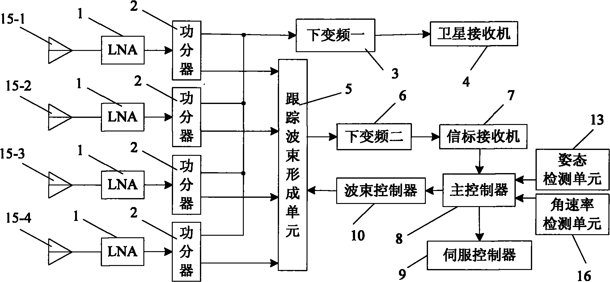
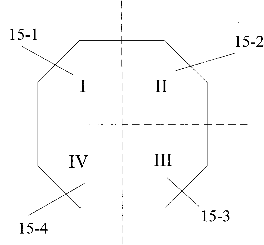
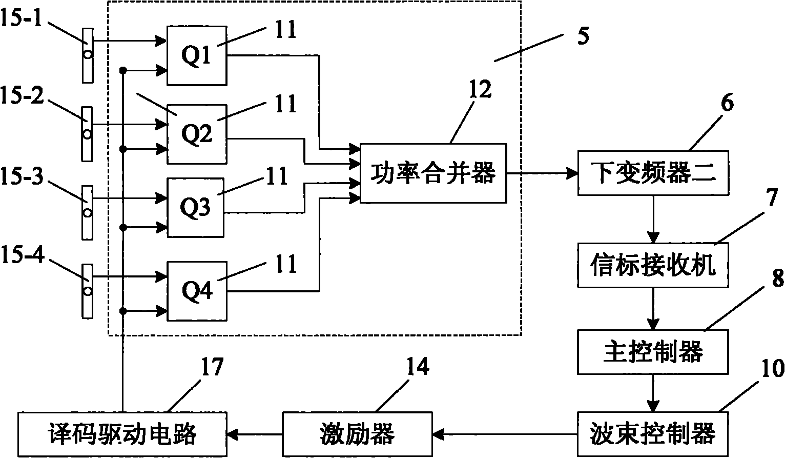
[0056] like figure 1 , figure 2 and image 3 A dual-beam pseudo-monopulse tracking system shown in motion includes a panel antenna, four low-noise amplifiers 1, four power dividers 2 connected to the four low-noise amplifiers 1, and four power dividers A down-converter-3 connected to one of the output ends of the four power splitters 2, a tracking beam-forming unit 5 connected to the other output ends of the four power dividers 2, a down-converter connected to the tracking beam-forming unit 5 Device 2 6, main controller 8, connected with down converter 2 6 and synchronously transmitting the AGC voltage used to represent the output signal strength of down converter 2 6 to the beacon receiver 7 of main controller 8, respectively The attitude detection unit 13 that detects the inclination angle of the azimuth axis and the pitch axis of the panel antenna in real time, the beam controller 10 controlled by the main controller 8, and the angular rate of movement of the mobile carr...


PUM


Abstract

The invention discloses a system and a method for tracking motion communication two-beam pseudo monopulse. The system comprises a plat antenna, four low-noise amplifiers, four power dividers, a down converter I, a tracking beam forming unit, a down converter II, a main controller, a beacon receiver, an attitude detecting unit, an angular rate detecting unit and a beam controller, wherein the down converter I is respectively connected with one output end of the four power dividers; the tracking beam forming unit is respectively connected with the other output end of the four power dividers; the down converter II and the main controller are connected with the tracking beam forming unit; the beacon receiver, the attitude detecting unit and the angular rate detecting unit are connected with the down converter II; the beam controller is controlled by a main controller; and the antenna is divided into four quadrant submatrixes. The method comprises the following steps of: detecting signals in real time, uploading the signals synchronously, generating two beams, and communicating and tracking by two beams synchronously. The invention has the advantages of simple design, convenient use and operation, high tracking precision, high tracking speed, simplicity and easy implementation, and enables the communication motion system to be free from the constraint of the main station and always track the target satellite by adopting the two beams.

Description

technical field [0001] The invention belongs to the technical field of satellite communication system antenna beam tracking, and in particular relates to a phased array antenna-based dual-beam pseudo-monopulse tracking system and tracking method. Background technique [0002] Satellite communication system in motion (referred to as "communication in motion") means that mobile carriers (such as automobiles, trains, airplanes, ships, etc.) equipped with satellite antennas can establish communication links with stationary satellites (ie geostationary satellites - target satellites) It is also a system that can keep the communication link open during the rapid movement of the carrier to achieve real-time communication. Because the distance between the stationary satellite and the ground is very long (about 36,000 kilometers), it is necessary to use a high-gain directional antenna to realize the broadband multimedia communication between the mobile carrier and the stationary sate...

Claims


Application Information

Patent Timeline
IPC IPC(8): G05D3/12
Inventor 贾维敏姚敏立沈晓卫赵鹏张峰干陈辉华朱丰超杨慧杰
Owner PLA SECOND ARTILLERY ENGINEERING UNIVERSITY
Learn More