Power capacitor

A technology of power capacitors and capacitors, which is applied to the terminals of fixed capacitors and components of fixed capacitors, etc., can solve the problems of multiple processing procedures, large ceramic specificity, fragile anti-pollution flashover performance, etc., and achieve simplified structure and processing procedures , save parts and assembly process, excellent effect of anti-fouling flashover performance

Active Publication Date: 2010-12-15
HEBEI GAOJING ELECTRICAL EQUIP
View PDF4 Cites 4 Cited by
  • Summary
  • Abstract
  • Description
  • Claims
  • Application Information

AI Technical Summary

Problems solved by technology

The terminal posts made of ceramics have many parts and need to be assembled one by one, so the processing technology is cumbersome and waste products are easy to appear; at the same time, it is a well-known fact that ceramics are large in proportion, fragile and have relatively poor anti-pollution flashover performance. Poor; so the structure of this traditional terminal still needs to be improved
[0003] In addition, the disadvantage of the high-voltage power capacitor made of this traditional ceramic terminal is that: when making the power capacitor, it is necessary to make the fixed mounting seat and punch out the mounting interface on the capacitor shell. Two separate processes, In addition, one welding is required when the fixed mounting base is installed on the ceramic insulator body, and another welding is required when the fixed mounting base is fixed on the mounting interface of the capacitor, resulting in more processing procedures, cumbersome operation and high cost

Method used


Image

  • Power capacitor
  • Power capacitor
  • Power capacitor

Examples


Embodiment 1

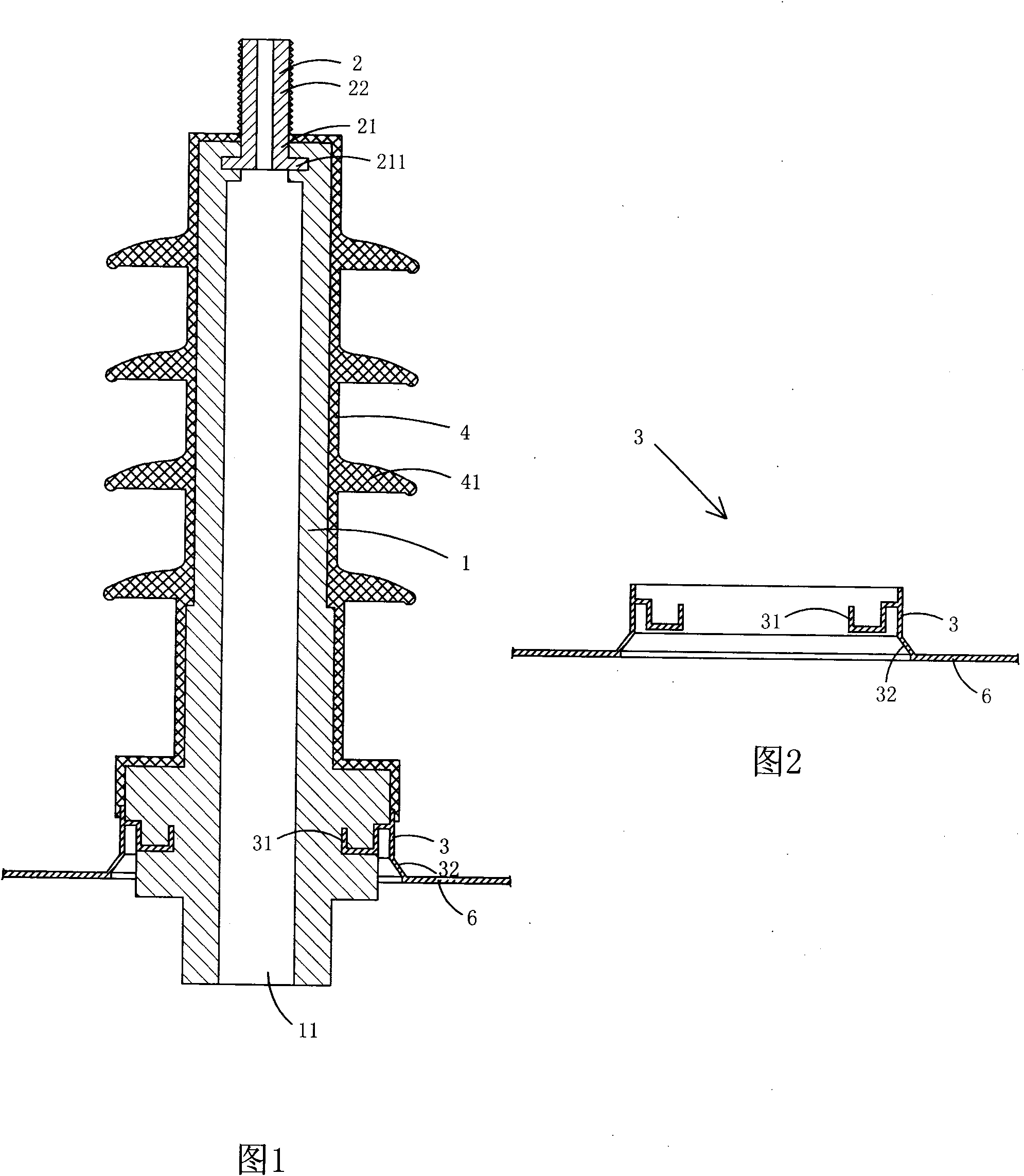
[0024] Figure 1 to Figure 2 A first embodiment of the invention is shown, in which figure 1 It is a half-sectional view of the first structure of the present invention; figure 2 yes figure 1 Half-section view of the metal mount in the power capacitor shown;

[0025] This embodiment is a terminal for power capacitors, see Figure 1 to Figure 2 , including a capacitor case 6 and a terminal 1 fixed on the capacitor case 6, the terminal 1 includes an insulator body 1, a metal terminal bolt 2 arranged on the top of the insulator body 1 and a metal terminal bolt 2 arranged on the insulator body 1 The metal mounting seat 3 at the bottom; the metal mounting seat 3 is a protruding piece directly formed on the capacitor case 6 by stamping; the insulator body 1 is made of composite insulating resin; the metal mounting seat 3 is provided with There is a plastic sealing part 31 for fixed connection with the insulator body 1, and a mounting part 32 for connecting with the capacitor ca...

Embodiment 2

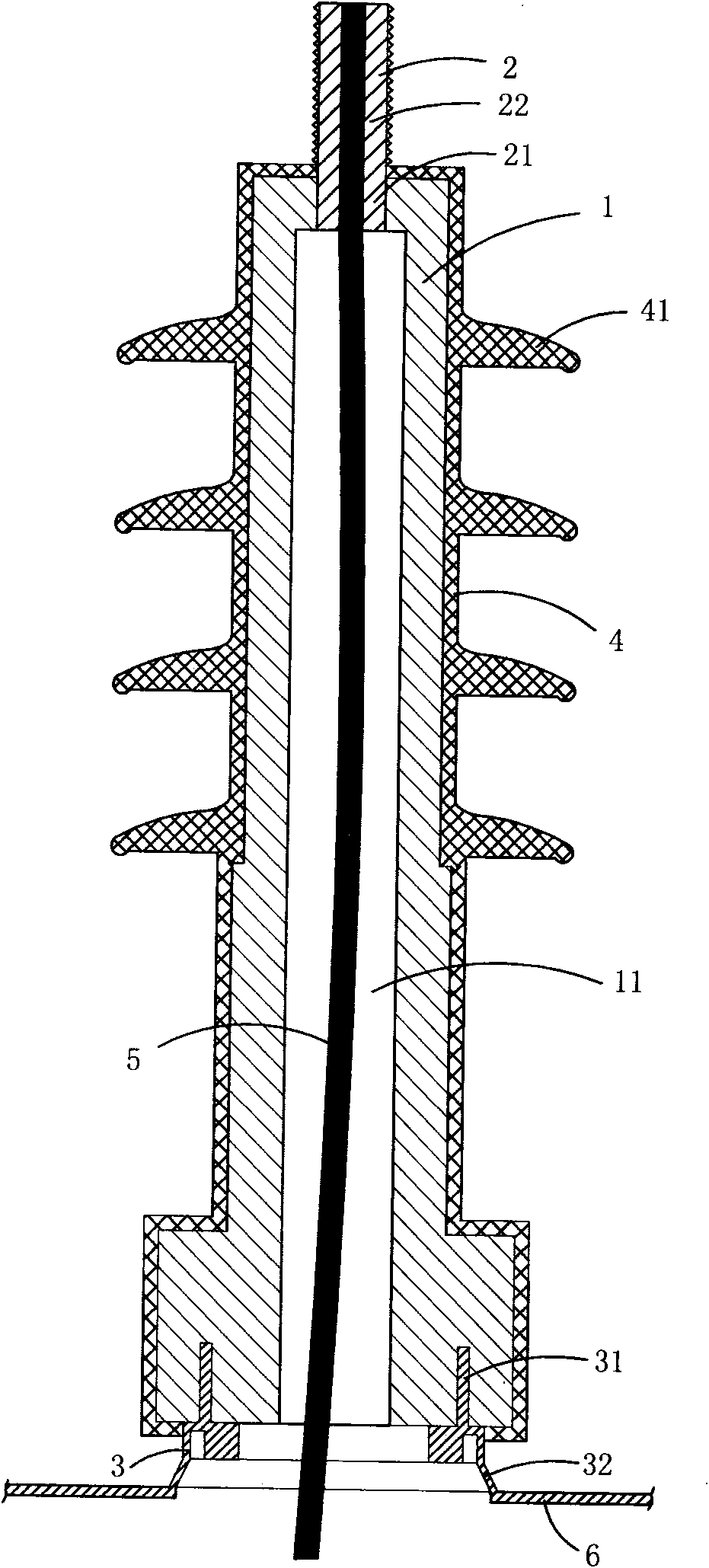
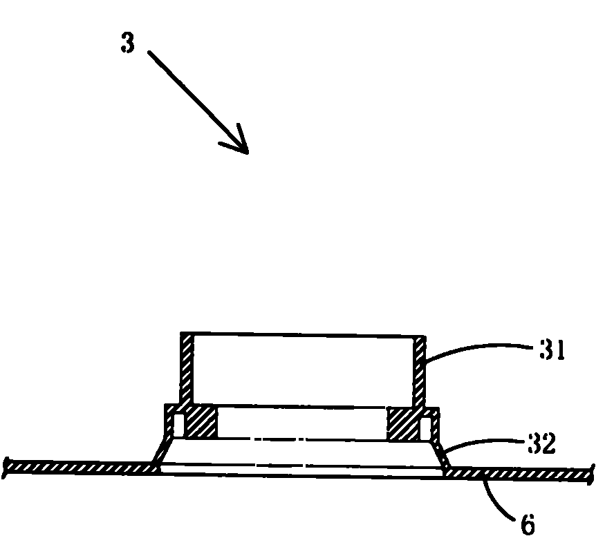
[0034] Figure 3 to Figure 4 A second embodiment of the invention is shown, in which image 3 It is a half-sectional view of the second structure of the present invention; Figure 4 yes image 3 Half cutaway view of the metal mount in the power capacitor shown.

[0035] This embodiment is basically the same as Embodiment 1, except that the top end of the plastic sealing part 31 protrudes upwards from the cavity surrounded by the mounting part 32 , and the mounting part 32 is located on the bottom wall of the insulator body 1 below.

[0036] The insulator body 1 is provided with an annealed copper wire 5 in its through hole 11 , the upper end of the annealed copper wire 5 is electrically connected to the metal connection bolt 2 , and the metal mounting base 3 is insulated from the annealed copper wire 5 .

[0037] The insulator body 1 is made of glass fiber reinforced epoxy resin; the metal mounting base 3 is made of stainless steel.

[0038] In addition, in this embodimen...


PUM


Abstract

The invention discloses a power capacitor comprising a capacitor casing and a bonding post fixed on the capacitor casing, wherein the binding post comprises an insulator body, a metal wiring bolt and a metal mounting seat, wherein the metal wiring bolt is arranged at the top end of the insulator body; the metal mounting seat is arranged at the lower part of the insulator body and is a male member which is directly formed on the capacitor casing; the insulator body is made of compound insulated resin; the metal mounting seat is provided with a plastic sealing part and a mounting part, wherein the plastic sealing part is fixedly connected with the insulator body; the mounting part is connected with the capacitor casing; and the plastic sealing part of the metal mounting seat is plastically sealed at the lower part of the insulator body by injection forming or compression molding forming, thereby being connected with the insulator body into a whole. The invention has the advantages of simplified processing process and favorable sealing performance.

Description

technical field [0001] The invention belongs to the technical field of structural design of power capacitors. Background technique [0002] The current power capacitors still mostly use ceramic insulators as the main terminal. The main reason is that most power capacitors need to have a relatively strict sealing performance in order to avoid internal liquid leakage. In addition, because most power capacitors are compared with other high-voltage electrical appliances , the price is relatively low, in order to maintain competitiveness, it has to use cheap ceramics as the main body of the terminal. The terminal includes a ceramic insulator body, a wiring assembly welded on the top of the insulator, and a fixed mounting seat welded and fixed on the lower part of the insulator. When manufacturing and assembling this type of terminal, it is necessary to fix the fixed mounting seat made of metal on the outer wall of the insulator body by welding; A tubular mounting interface, and...

Claims


Application Information

Patent Timeline
Patent Type & Authority Applications(China)
IPC IPC(8): H01G4/228H01G4/236
Inventor 赵牧青
Owner HEBEI GAOJING ELECTRICAL EQUIP
Why Eureka
Try Eureka