Method and device for improving specific proportion load efficiency of power source

A technology of load efficiency and power supply, applied in the field of power supply, can solve the problems of long startup time of dormant modules, insignificant overall efficiency of power supply system, energy waste, etc., so as to reduce the risk of power system and load power failure, and improve power output. Efficiency, fast load response effect

Active Publication Date: 2014-11-05
ZTE CORP
View PDF3 Cites 0 Cited by
  • Summary
  • Abstract
  • Description
  • Claims
  • Application Information

AI Technical Summary

Problems solved by technology

For example: the rated load efficiency of the power supply is 94%, while the customer’s usual load rate is 40%, the actual load efficiency of the power supply is 90%, which is 4% less than the rated load efficiency of the power supply, and in the case of a high-power power supply system, the efficiency difference is 4%. means a huge waste of energy
[0005] To address the above problems, in the prior art, in the parallel connection of multiple power supply modules (systems), the usual method for small loads is to let some of the modules sleep, but this method has the following defects: when the load suddenly increases In some cases, the dormant module will have a long startup time, and there is a risk of power failure
[0006] The existing technology also adopts a hot backup method, that is, to control the output of some modules so that they do not output, but only allow the modules that can just provide load energy to have output. Although the system response time of this hot backup method is relatively fast, However, because the power device also consumes in the case of no load, this method is not obvious for improving the overall efficiency of the power system

Method used


Image

  • Method and device for improving specific proportion load efficiency of power source
  • Method and device for improving specific proportion load efficiency of power source
  • Method and device for improving specific proportion load efficiency of power source

Examples


Embodiment Construction

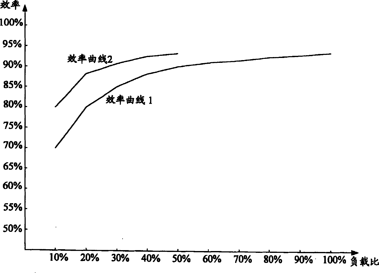
[0049] The solution of the embodiment of the present invention is mainly to select a corresponding number of sub-power circuits in the preset power circuit to provide the required power to the load through the detected actual load of the user, so as to avoid the power circuit of the power supply system in the prior art, regardless of the load The size, unnecessary power loss caused by all parallel power branches working at the same time, improves the load efficiency of the power system.

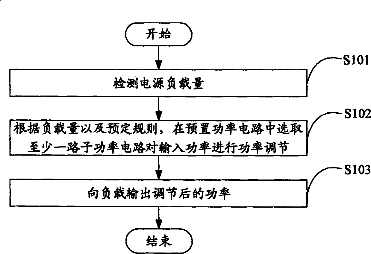
[0050] Such as figure 1 As shown, an embodiment of the present invention proposes a method for improving the load efficiency of a specific ratio of a power supply, including:

[0051] Step S101, detecting the power load;

[0052] Step S102, according to the load and predetermined rules, select at least one sub-power circuit in the preset power circuit to regulate the input power;

[0053] Step S103, outputting the regulated power to the load.

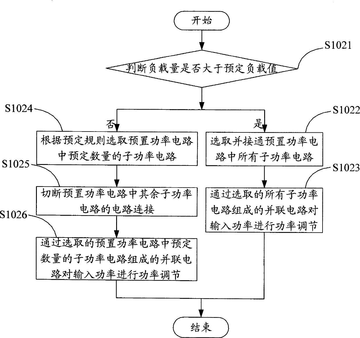
[0054]In the above step S101 to step S103, in...


PUM


Abstract

A method for improving a specific proportion load efficiency of a power supply and an apparatus thereof. The method includes the following steps: detecting the load capacity of the power supply (101); selecting at least one sub-power-circuit from preset power circuits to perform the power regulation of an input power according to the load capacity and predetermined rules (102); outputting the regulated power to a load (103). In the method, according to the detected load capacity, the selected corresponding sub-power-circuits in the preset power circuits are switched to regulate the input power so as to supply the load with a required power. The power loss of the power supply is reduced, and the output efficiency of the power supply is improved. Moreover, switching may further be performed among the sub-power-circuits according to a preset return difference value, thus a power supply system risk and a load power-fail risk are lowered due to frequent switching among the sub-power-circuits.

Description

technical field [0001] The invention relates to the technical field of power supplies, in particular to a method and device for improving the load efficiency of a specific ratio of a power supply. Background technique [0002] At present, energy shortage is a common concern of the whole society. How to save the existing non-renewable energy such as coal, oil, natural gas in the short term, how to find alternative energy and improve the utilization rate of existing energy has become an urgent problem to be solved. . [0003] The output efficiency of existing power electronic equipment and power supply equipment (including DC power supply equipment and AC power supply equipment, etc.) usually increases with the increase of load. When the output power is rated load (100% load), the efficiency The highest, but for a specific user, for the purpose of backup or use safety, the output power required by the load generally does not exceed 50%. [0004] Therefore, for the user, the ...

Claims


Application Information

Patent Timeline
Patent Type & Authority Patents(China)
IPC IPC(8): H02J3/06
CPCY02B70/1491H02M7/23H02M7/487H02M2001/0048H02M2001/007H02M1/0048H02M1/007Y02B70/10
Inventor 阎建法张凤英
Owner ZTE CORP
Why Eureka
Try Eureka