Velocity transducer output signal analog device and method

A speed sensor and output signal technology, applied in the field of electronics, can solve the problems of difficulty in supporting the simulation of the amplitude characteristics of the speed pulse signal, difficult to meet the specific requirements of the output signal of the speed sensor, and high price

Active Publication Date: 2010-12-15
TRAFFIC CONTROL TECH CO LTD
View PDF0 Cites 13 Cited by
  • Summary
  • Abstract
  • Description
  • Claims
  • Application Information

AI Technical Summary

Problems solved by technology

Equipment that generates more than four channels of signals not only needs to be customized, but also more expensive
In addition, the output signal amplitude of commercial signal generators is mostly only 10 volts, which is difficult to support the simulation of the amplitude characteristics of speed pulse signals
Therefore, the commercial signal generator has the problem that it is difficult to meet the specific requirements of the speed sensor output signal, and the cost is high, so it is not suitable to be used as a speed pulse signal simulator

Method used


Image

  • Velocity transducer output signal analog device and method
  • Velocity transducer output signal analog device and method
  • Velocity transducer output signal analog device and method

Examples


Embodiment 1

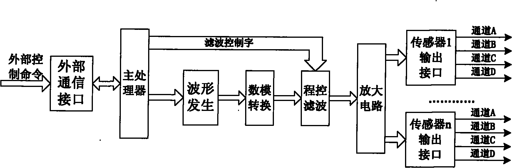
[0068] This embodiment specifically describes the situation of using the technical solution of the present invention to simulate the output signal of a speed sensor whose output waveform is a sine wave.

[0069] Such as figure 1 As shown, the schematic diagram of the speed sensor output signal simulation method and device of this embodiment is given. The speed sensor output signal simulator completes the interface expansion of information interaction with external equipment through the external communication interface module, so that the system can receive external control commands. Ability. The main processor module communicates with external devices through the external communication interface module, and receives external control commands, including the signal waveform type, speed value, direction and channel number that should be output at the current moment. The main processor module calculates the frequency value of the signal that should be output at the current moment...

Embodiment 2

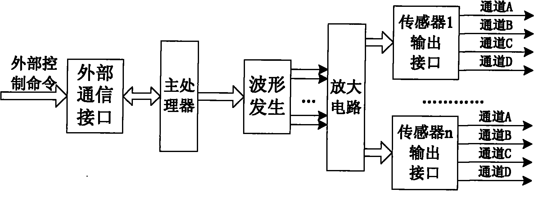
[0071] The following specifically describes the situation of using the technical solution of the present invention to simulate the output signal of a speed sensor whose output waveform is a square wave.

[0072] Such as figure 2As shown, the schematic diagram of the speed sensor output signal simulation method and device of this embodiment is given. The main difference between this embodiment and the technical solution of Embodiment 1 is that the digital-to-analog conversion module and the program-controlled filter module can be omitted. This is because when the output waveform is a square wave, the amplitude of the output signal has only two values ​​of high level or zero level, so there is no need to use digital quantities to represent the output signal amplitude, and then there is no need to include a digital-to-analog conversion module and a program control filter module. Another difference in the technical solution between this embodiment and Embodiment 1 is the transmi...

Embodiment 3

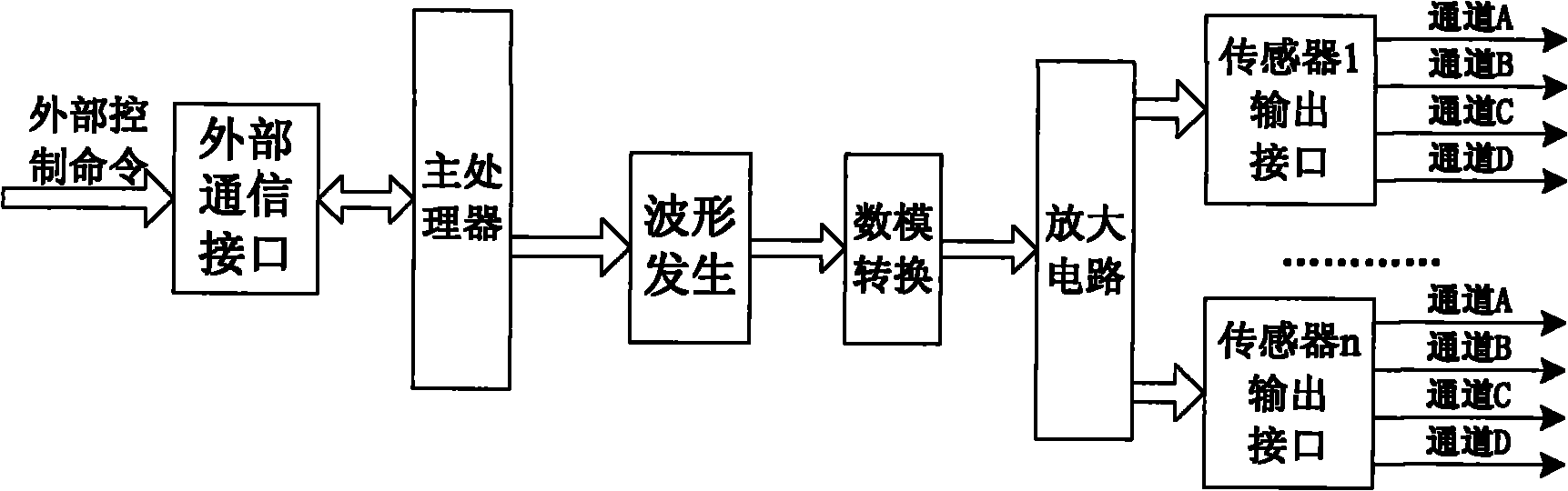
[0074] The following specifically describes the situation of using the technical solution of the present invention to simulate the output signal of a speed sensor whose output waveform is a specified waveform (such as a triangle wave).

[0075] Such as image 3 As shown, a schematic diagram of the speed sensor output signal simulation method and device of this embodiment is given. The main difference between this embodiment and the technical solution of Embodiment 1 lies in the waveform generation module and the program-controlled filtering module. When the output waveform is other specified waveform (such as: triangular wave), the output waveform phase-amplitude data table stored in the waveform generation module should be replaced with the data table corresponding to the specified waveform, so that the current output signal amplitude value obtained after table lookup is For the specified waveform form. Correspondingly, since the output waveform is no longer a sine wave, the...


PUM


Abstract

The invention relates to velocity transducer output signal analog device and method, belonging to the technical field of electronics. Aiming at overcoming the defects of the prior art and in order to enlarge the application range of the velocity transducer output signal analog device, the technical scheme of the invention comprises the following steps of: firstly, receiving an external control command for formulating the signal characteristics to be output by the current velocity transducer by using a main processor module and an external communication interface module; then, generating the amplitude of the current output signal in real time by using a waveform generating module, and acquiring the analog quantity value of the amplitude of the output signal; subsequently, smooth filtering the waveform of the signal through a program controlled filtering module; and finally, amplifying the amplitude of the signal to be output by the current velocity transducer by using a power amplifying module. The technical scheme realizes the analog and the simulation of various velocity transducer output signals, and the invention has the characteristics of high frequency conversion velocity, easy realization, easy replication, low cost, high price-to-performance ratio and the like.

Description

technical field [0001] The invention relates to the field of electronic technology, in particular to a speed sensor output signal simulation device and method. Background technique [0002] A speed sensor is a device that converts changes in speed information into changes in power, and is widely used in control systems such as automobile control and robots. Especially in the field of rail transit, the correct execution of the train operation control system largely depends on the correct collection and processing of train speed information. Therefore, the speed sensor has become an important part of the train operation control system. The speed sensor output signal simulator is a device that can flexibly simulate the output signal of the speed sensor, and can provide a speed information source for devices that use speed information as input information. Taking the field of rail transit as an example, in order to facilitate the debugging, testing and verification of complex t...

Claims


Application Information

Patent Timeline
Patent Type & Authority Applications(China)
IPC IPC(8): H03K3/02
Inventor 袁磊耿家骏唐涛李开成刘雨魏国栋
Owner TRAFFIC CONTROL TECH CO LTD
Why Eureka
Try Eureka