Device and method for detecting co-optical system and co-detector glimmer passive and laser active compound imaging

An optical system and composite imaging technology, applied in the direction of measuring devices, radio wave measuring systems, instruments, etc., can solve the problems of low integration, complex information fusion, and low fusion, and achieve the effect of fast search

Inactive Publication Date: 2010-12-22
HARBIN INST OF TECH
View PDF3 Cites 13 Cited by
  • Summary
  • Abstract
  • Description
  • Claims
  • Application Information

AI Technical Summary

Problems solved by technology

[0003] In order to solve the problems of low integration, complex information fusion and low fusion degree of existing active-passive compound imaging devices, the

Method used


Image

  • Device and method for detecting co-optical system and co-detector glimmer passive and laser active compound imaging
  • Device and method for detecting co-optical system and co-detector glimmer passive and laser active compound imaging

Examples


specific Embodiment approach 1

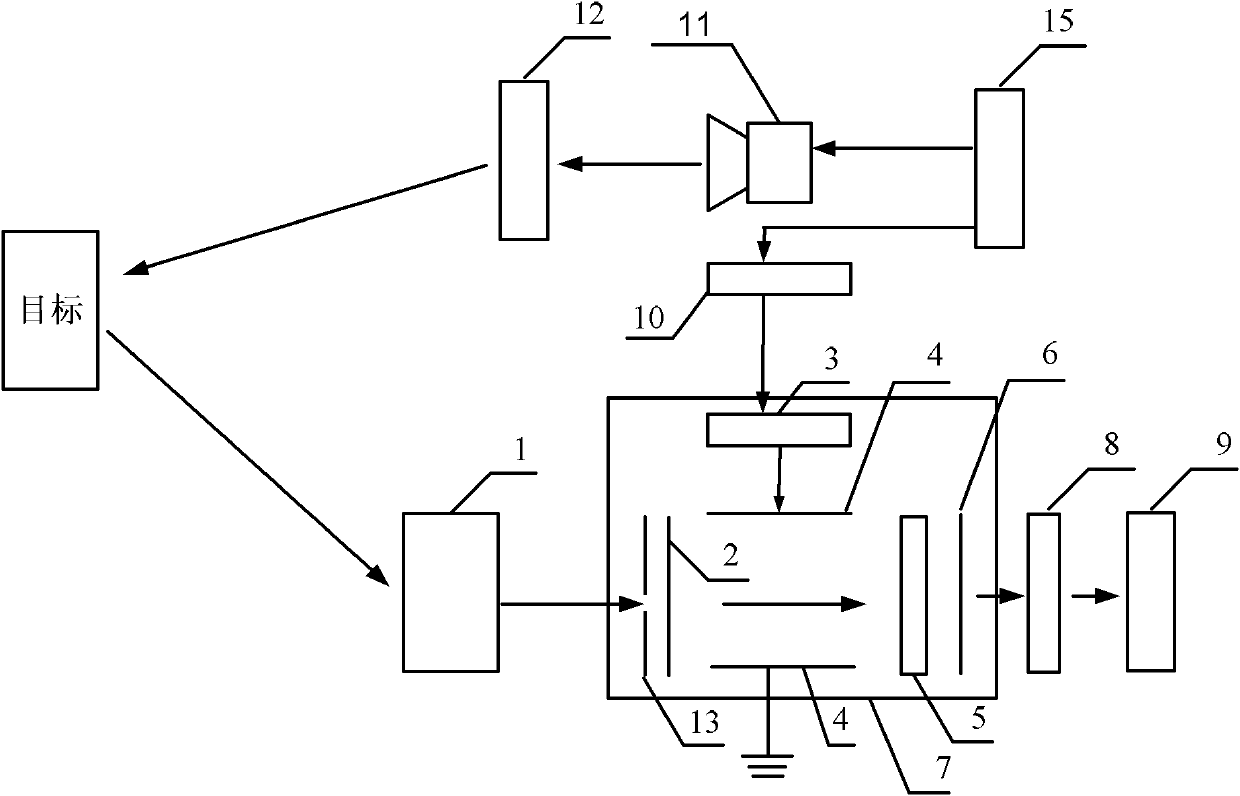
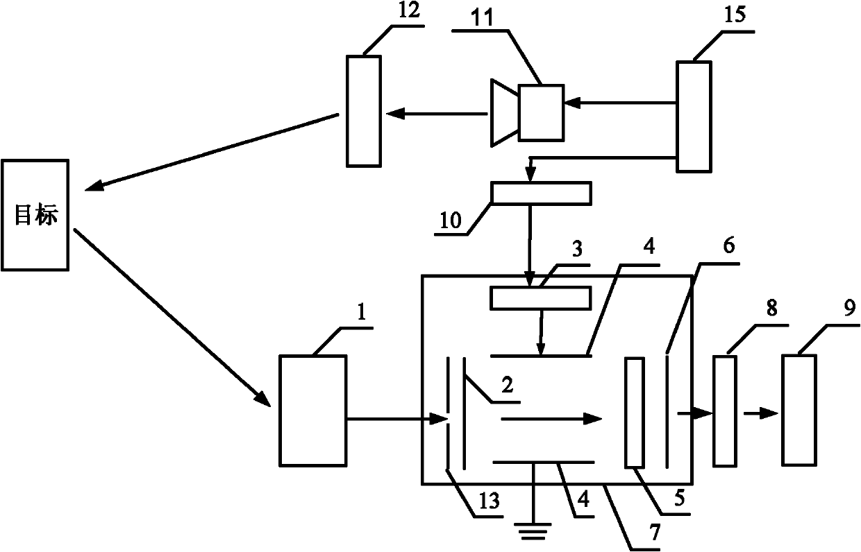
[0013] Embodiment 1: Combining figure 1 In this embodiment, a detection device for low-light passive and laser active composite imaging with a common optical system and a common detector includes a receiving optical system 1, a streak tube detector 7, a coupling lens 8, a CCD camera 9, and a delay trigger circuit 10. , laser 11, emission optical system 12 and power supply 15, the laser 11 is arranged on the rear end surface of the emission optical system 12, so that the laser light emitted by the laser 11 becomes a parallel line light output after beam expansion by the emission optical system 12, and the parallel line After the light is reflected by the target, it is incident on the receiving optical system 1; the receiving optical system 1, the streak tube detector 7, the coupling lens 8 and the lenses of the CCD camera 9 are arranged in sequence, and the photocathode 2 in the streak tube detector 7 is arranged in the receiving optical system. On the focal plane of the optica...

specific Embodiment approach 2

[0014] Embodiment 2: This embodiment is a further description of Embodiment 1. The streak tube detector 7 includes a slit diaphragm 13 , a photocathode 2 , a scanning circuit 3 , an electrode 4 , a microchannel plate 5 and a phosphor screen 6 , the two parallel plates of the electrode 4 are arranged opposite to each other, the slit diaphragm 13, the photocathode 2, the microchannel plate 5 and the phosphor screen 6 are arranged coaxially in turn, and the slit diaphragm 13, the photocathode 2, the microchannel plate 5 and The phosphor screen 6 is perpendicular to the two parallel plates of the electrode 4, the slit direction of the slit diaphragm 13 is parallel to the setting direction of the two parallel plates of the electrode 4, and the signal output end of the scanning circuit 3 is parallel to one of the electrodes 4. The signal input ends of the parallel polar plates are connected, and the signal input end of the other parallel polar plate of the electrode 4 is grounded.

specific Embodiment approach 3

[0015] Embodiment 3. This embodiment is a further description of Embodiment 1 or 2. The streak tube detector 7 adopts a single-slit streak tube. The dynamic spatial resolution of the single-slit streak tube is ≥15lp / mm, and The resolving power is -15 J / mm 2 .


PUM

PropertyMeasurementUnit
Pulse widthaaaaaaaaaa

Abstract

The invention provides a device and a method for detecting co-optical system and co-detector glimmer passive and laser active compound imaging, belonging to the field of imaging radar detecting devices and solving the problems of low integration level, complicated information fusion and low fusion level of the traditional active and passive compound imaging device. Light emitted by an optical system of the device can be focused on a photocathode of a stripe tube detector, a coupling lens receives the light emitted from a fluorescent screen of the stripe tube detector, and then the light is shot by a CCD (Charge Coupled Device) camera. The method is realized by the detecting device based on the co-optical system and co-detector glimmer passive and laser active compound imaging and comprises the following steps of: firstly making a laser not emit light to obtain a glimmer passive image of a target; secondly, making the laser emit the light to obtain a laser active four-dimensional imageof the target; and thirdly, compounding the glimmer passive image and the laser active four-dimensional image to acquire a co-optical system and co-detector information fusion image. The invention issuitable for the field of glimmer passive and laser active compound imaging.

Description

technical field [0001] The invention relates to the field of imaging radar detection devices, in particular to a detection device and method for low-light passive and laser active composite imaging. Background technique [0002] At present, there are mainly two ways of active and passive composite imaging. One is non-common optical system and non-common detector, that is, active and passive imaging has its own optical system and detector; the other is common optical system and non-common detector. , that is, the active and passive imaging share the same optical system, but still need two detectors. Since the above two active and passive composite imaging methods cannot share a set of optical systems and the same detector, the integration of the imaging detection device is not high, and due to the different field angles of the optical systems for active and passive imaging and the different resolutions of the detectors , which leads to the complexity of the fusion algorithm ...

Claims


Application Information

Patent Timeline
IPC IPC(8): G01S7/481G01S17/89
Inventor 孙剑峰王骐梁小雪魏靖松郜键
Owner HARBIN INST OF TECH
Why Eureka
Try Eureka