Projection system with laser speckle removal function

A projection system and laser speckle technology, applied in the field of projection systems, can solve the problems of low optical fiber beam coupling efficiency, reduced laser energy utilization, energy loss, etc., to achieve good speckle elimination effect, laser speckle elimination, energy small loss effect

Inactive Publication Date: 2010-12-22
FUJIAN NORMAL UNIV
View PDF8 Cites 15 Cited by
  • Summary
  • Abstract
  • Description
  • Claims
  • Application Information

AI Technical Summary

Problems solved by technology

[0003] Among the published patents such as 200510089116.8 and 200510115472.2, such as image 3 , as shown in 4, are all lighting systems that effectively reduce or eliminate speckle by dividing the beam emitted from the laser source into sub-beams and averaging the sub-beams temporally or spatially, but this type of lighting system will suffer from diffractive optical elements Factors such as processing will cause a certain depolarization effect, which will lose part of the ene

Method used


Image

  • Projection system with laser speckle removal function
  • Projection system with laser speckle removal function
  • Projection system with laser speckle removal function

Examples


Embodiment 1

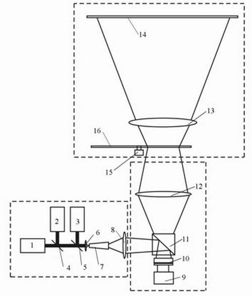
[0024] Example 1: Reference figure 1 ,

[0025] The projection system includes a laser lighting system, an imaging system and a projection objective lens system. The laser lighting system consists of RGB three-color lasers 1, 2, and 3, beam combiners 4, 5 that make the three-color lasers synthesize the same beam of light sources, and a converging lens 6. Homogenizing tube 7 and imaging lens group 8 are made up, and imaging system is made up of LCOS chip 10 and its drive circuit 9, polarization beam splitter prism 11 and imaging lens group 12, projection objective lens system is made up of projection objective lens group 13 and screen 14, and described imaging A random phase photo 16 is arranged between the lens group 12 and the projection objective lens group 13 to rotate by the rotating mechanism 15 or to reciprocate by the moving mechanism.

[0026] The RGB lasers 1, 2, and 3 collimate and output lasers of different wavelengths, and synthesize a beam of light through the b...

Embodiment 2

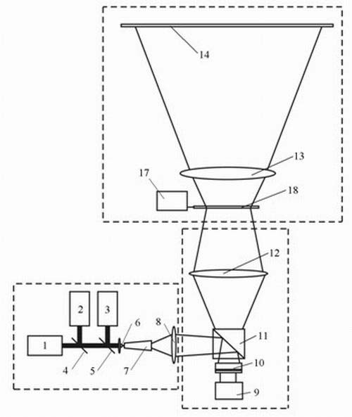
[0033] Example 2: Reference figure 2 ,

[0034] The projection system includes a laser lighting system, an imaging system and a projection objective lens system. The laser lighting system consists of RGB three-color lasers 1, 2, and 3, beam combiners 4, 5 that make the three-color lasers synthesize the same beam of light sources, and a converging lens 6. Homogenizing tube 7 and imaging lens group 8 are made up, and imaging system is made up of LCOS chip 10 and its drive circuit 9, polarization beam splitter prism 11 and imaging lens group 12, projection objective lens system is made up of projection objective lens group 13 and screen 14, and described imaging A liquid crystal cell 18 is arranged between the lens group 12 and the projection objective lens group 13 and is rotated or moved by a drive circuit 17 .

[0035] The RGB lasers 1, 2, and 3 collimate and output lasers of different wavelengths, which are synthesized by the beam combining mirrors 4 and 5, and the convergi...


PUM


Abstract

The invention provides a projection system with a laser speckle removal function. The system consists of a laser lighting system and two imaging systems, wherein, the laser lighting system composed of an RGB three-color laser and a uniform light tube provides a uniform lighting source for LCOS imaging; each imaging system composed of a beam-splitting prism, an LCOS chip, a drive circuit and an imaging lens forms an LCOS image on a random phase plate with high transmittance; when the random phase plate rotates in a high speed, the LCOS image thereon is formed on a screen through a projection lens, and outgoing beams of the random phase plate can be changed from linearly polarized light into elliptically polarized light due to different random phases thereof by adopting the random phase plate with a certain double refraction property; and by means of a time average principle and polarized light speckle characteristics, laser speckles can be greatly reduced to provide good image quality.

Description

technical field [0001] The invention relates to a projection system with the function of eliminating laser speckles. Background technique [0002] The characteristics of laser monochromaticity, strong directionality and high brightness make laser as a light source for projection display have the advantages of vivid picture color, clear image, and suitable for large-screen display. However, due to its good monochromaticity and long coherence length, various interference effects will occur on the optical surfaces of the projection system, forming a large number of background stray interference fringes and speckle noise. reduce. In order to improve the image quality of laser projection display, the design of suppressing laser speckle is very necessary. [0003] Among the published patents such as 200510089116.8 and 200510115472.2, such as image 3 , as shown in 4, are all lighting systems that effectively reduce or eliminate speckle by dividing the beam emitted from the laser...

Claims


Application Information

Patent Timeline
IPC IPC(8): G02B5/30G02B27/48G02B27/18G03B21/20G02F1/1335
Inventor 李高明邱怡申李晖林峰
Owner FUJIAN NORMAL UNIV
Why Eureka
Try Eureka