
Repetitive motion planning method for redundant manipulator

A technology of repetitive motion and robotic arm, applied in the direction of manipulators, manufacturing tools, etc., can solve the problems of not considering the acceleration limit, physical damage of the mechanical arm, and failure to meet the requirements of the mechanical arm.

Inactive Publication Date: 2010-12-29
SUN YAT SEN UNIV
View PDF4 Cites 52 Cited by
  • Summary
  • Abstract
  • Description
  • Claims
  • Application Information

AI Technical Summary

Problems solved by technology

[0003] Previous repetitive motion analysis methods were performed on the velocity layer, and the results obtained were all velocity values, which could not meet the requirements of some redundant manipulators with non-velocity control, and the solution method on the velocity layer did not consider Acceleration limit, the mechanical arm may be physically damaged due to exceeding the acceleration limit during the movement

Method used


Image

  • Repetitive motion planning method for redundant manipulator
  • Repetitive motion planning method for redundant manipulator
  • Repetitive motion planning method for redundant manipulator

Examples


Embodiment Construction

[0019] The present invention will be further described below in conjunction with the drawings.

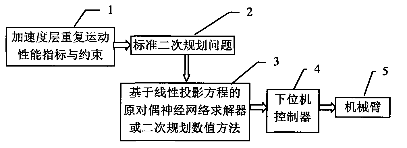
[0020] figure 1 The redundant manipulator repetitive motion planning method shown is mainly composed of acceleration layer repetitive motion performance indicators and constraints 1, standard quadratic programming 2, primal dual neural network solver based on linear projection equations or quadratic programming numerical method 3, lower level The machine controller 4 and the robot arm 5 are composed.

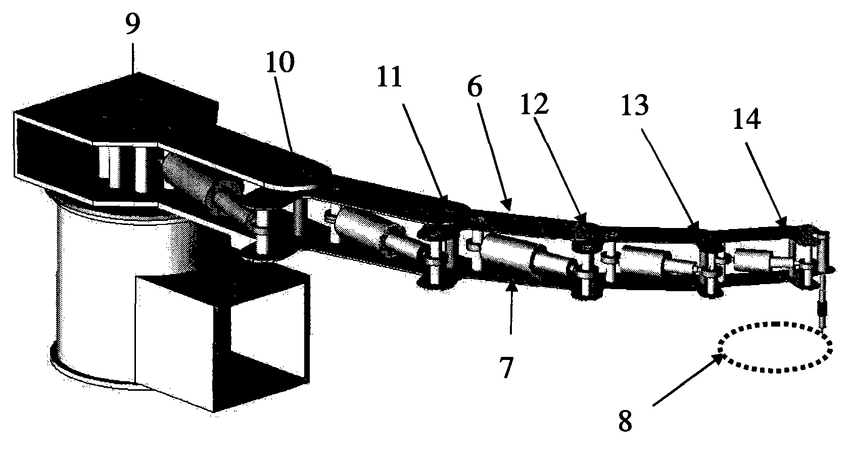
[0021] figure 2 The robot arm shown to implement the present invention is a plane with six degrees of freedom. The mechanical arm is composed of six links, which are composed of joint 9, joint 10, joint 11, joint 12, joint 13 and joint 14.

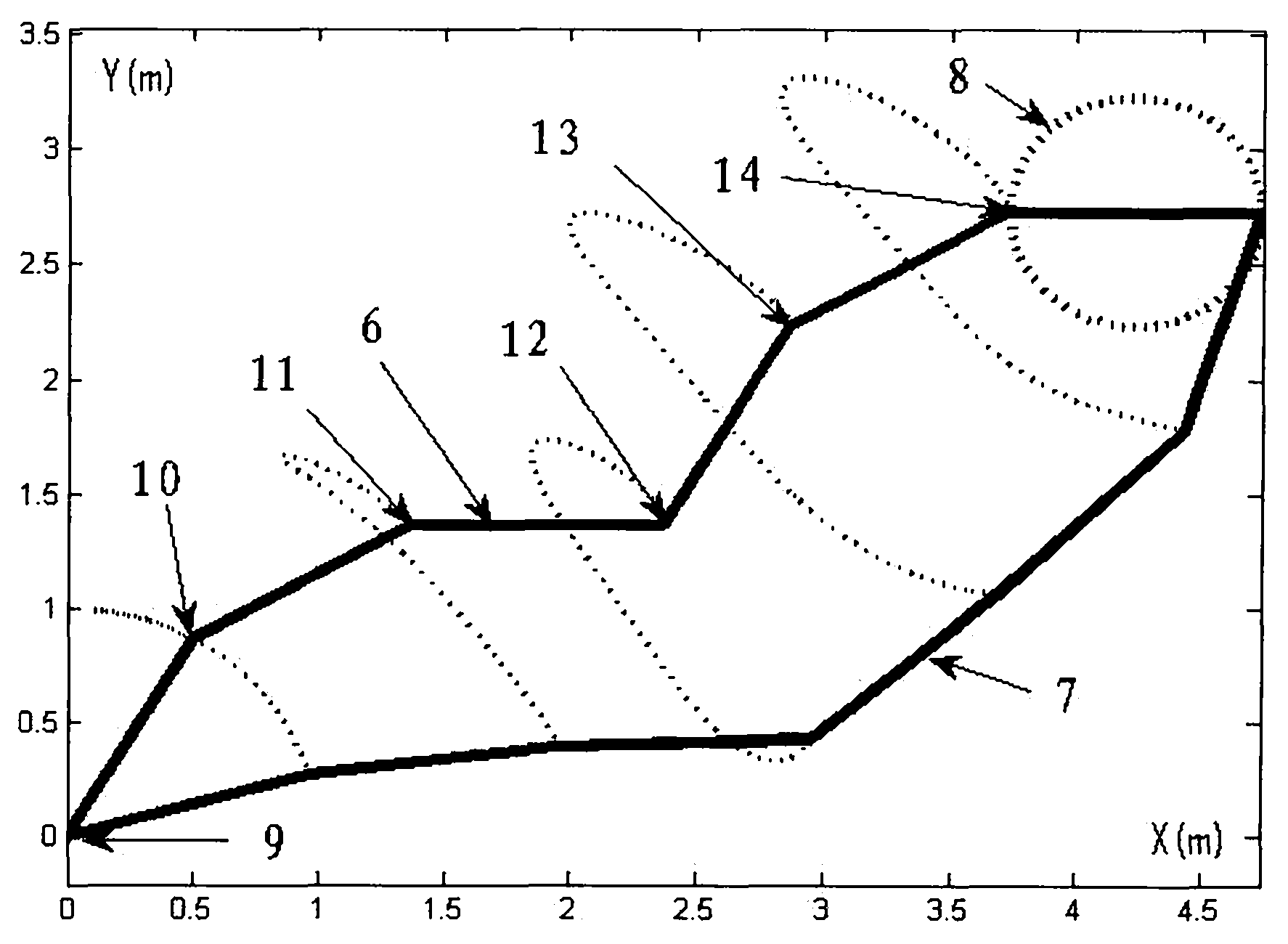
[0022] image 3 The schematic diagram of the non-repetitive motion of the robotic arm shown. Given that the end task 8 is a closed curve, the robotic arm starts to execute from the initial position 6. After completing the task, the robotic arm stops...


PUM


Abstract

The invention provides a repetitive motion planning method for a redundant manipulator, which comprises the following steps of: 1) resolving a manipulator repetitive motion scheme on an acceleration layer by adopting quadratic model optimization through an upper computer, designing the minimum performance index as repetitive motion, and restraining by an acceleration Jacobian equation, a joint angle limit, a joint speed limit and a joint acceleration limit; 2) converting the quadratic model optimization in the step 1) into standard quadratic programming; 3) solving the standard quadratic programming in the step 2) by using a linear projection equation-based primal-dual neural-network solver or quadratic programming numerical method; and 4) transmitting a solving result in the step 3) to acontroller of a lower computer for driving the manipulator to move. The method realizes the repetitive motion of the manipulator on the acceleration layer, has good control effect on the redundant manipulator inconvenient to control, and can effectively prevent the manipulator from exceeding the limits and being physically damaged according to various joint limits.

Description

Technical field [0001] The invention relates to the field of redundant manipulator control, in particular to an inverse kinematics solution method of a redundant manipulator. Background technique [0002] Redundant manipulator is a terminal active mechanical device with a degree of freedom greater than the minimum degree of freedom required by the task space. Its motion tasks include welding, painting, assembly, excavation and drawing, etc., and are widely used in equipment manufacturing, product processing, and machine operations And other national economic production activities. The inverse kinematics problem of the redundant manipulator refers to the problem of determining the joint angle of the manipulator with the known end pose of the manipulator. When the end task of the redundant manipulator is a closed curve, its various joints may not return to the initial position. This phenomenon is called the joint angle deviation phenomenon, or the problem of non-repetitive motion;...

Claims


Application Information

Patent Timeline
Patent Type & Authority Applications(China)
IPC IPC(8): B25J13/00
Inventor 张雨浓张智军朱虹
Owner SUN YAT SEN UNIV
Learn More