Electromagnetic braking translation-type rolling plate clamp

An electromagnetic braking and translational technology, which is applied in the direction of transmission devices, friction transmission devices, load suspension components, etc., can solve the problems of processing and assembly errors of supporting beam processing parts, clamp arm protection devices that cannot be moved by suspended objects at the same time, Problems such as inaccurate reset

Active Publication Date: 2010-12-29
JULI SLING
View PDF5 Cites 7 Cited by
  • Summary
  • Abstract
  • Description
  • Claims
  • Application Information

AI Technical Summary

Problems solved by technology

The coiling clamp driven by the three-screw form has the following disadvantages: the transmission screw is easily bent and deformed after being stressed, resulting in the inability to open the clamp; The situation of the motor occurs; when the clamp arm clamps the steel coil or aluminum coil, the protection measures on the clamp arm are not in place, which is easy to damage the suspended object
The clamp in the form of longitudinal transmission of rack and pinion has the following disadvantages: the supporting beam is box-shaped connection, there are many processed parts, and the cost is high; due to the large number of processed parts, there are accumulated errors and it is not easy to maintain; there are errors in the processing and assembly of the supporting beam processed parts, Easy to deform; the reducer is assembled in the middle of the beam, and the replacement of the motor is inconvenient
The arm protection device of the two types of clamps mentioned above cannot move simultaneously with the suspended object, resulting in damage to the suspended object, which is also inaccurate in reset and inconvenient for maintenance.

Method used


Image

  • Electromagnetic braking translation-type rolling plate clamp
  • Electromagnetic braking translation-type rolling plate clamp
  • Electromagnetic braking translation-type rolling plate clamp

Examples


Embodiment Construction

[0016] The present invention will be further described below in conjunction with accompanying drawing and specific embodiment:

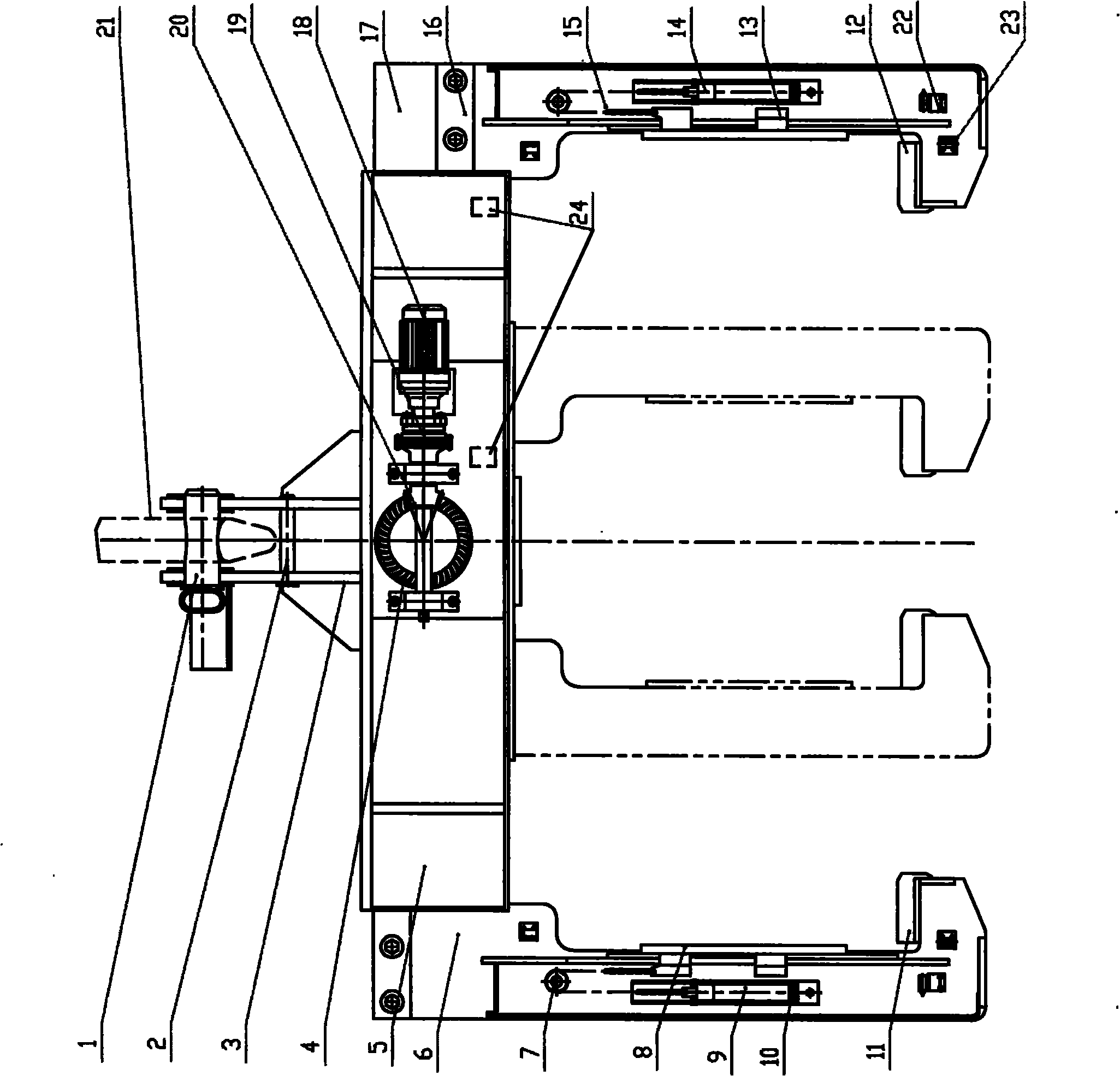
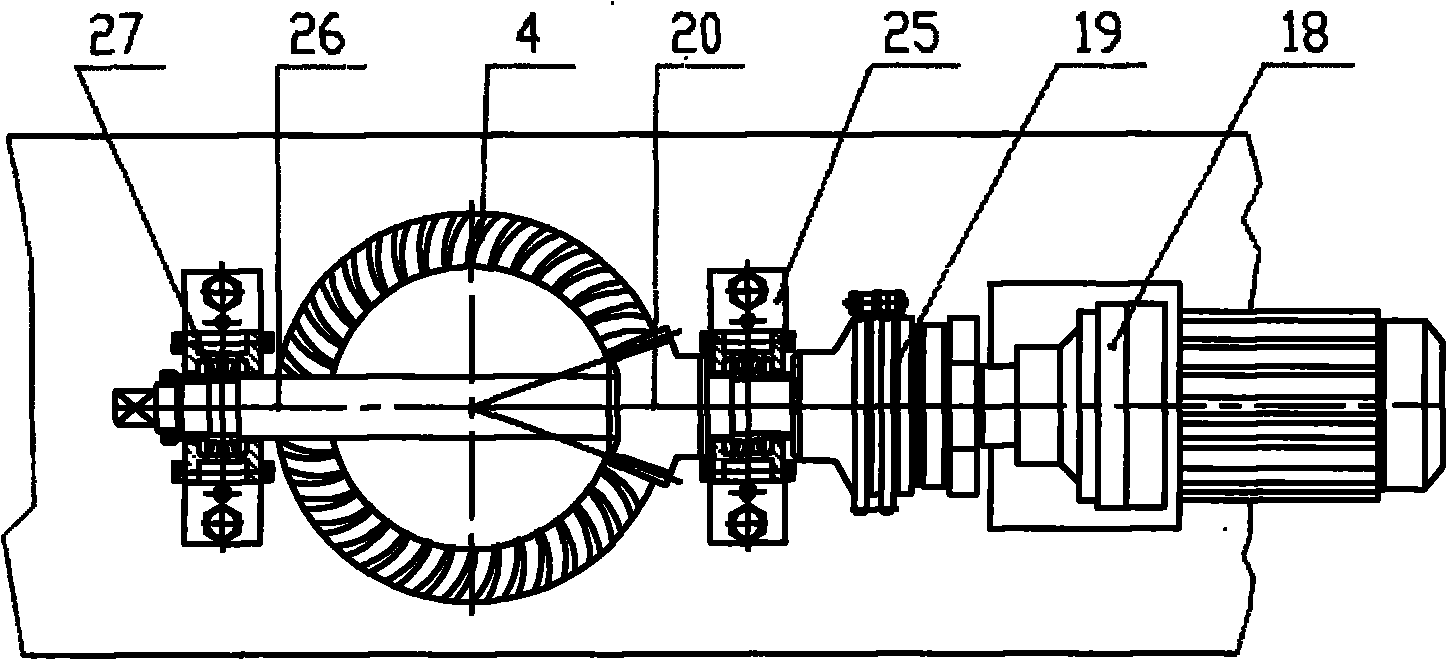
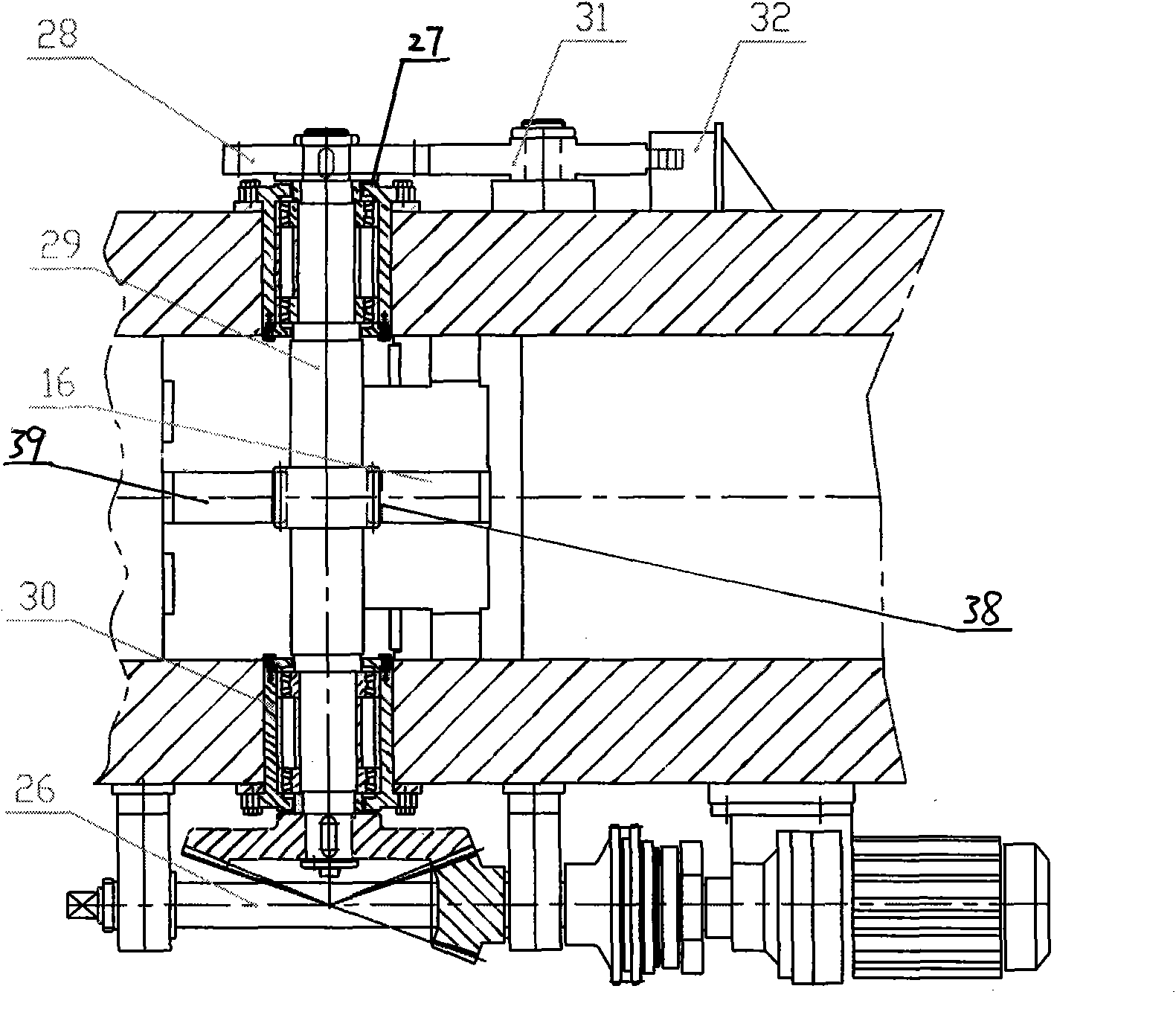
[0017] Such as figure 1 with figure 2 As shown, this embodiment includes a lifting device, a driving device, an electromagnetic braking device, a support beam, left and right clamp arms, a protection device, a protection device for the clamp arms and an electrical system.

[0018] Hoisting device is installed on the top of supporting crossbeam 5, and it comprises hanging shaft 1, hanging shaft bracket, lifting bracket 3 and anti-off shaft 2. The lifting frame 3 that there are two hanging lugs on the upper end is connected with the support beam 5 with the anti-off shaft 2, and the hanging shaft bracket is installed on one side of the lifting frame 3. When not hoisting, the suspension shaft 1 is positioned in the suspension shaft bracket, and during hoisting, the suspension shaft 1 moves forward and is placed in two lugs and the suspension hook 21 o...


PUM


Abstract

The invention discloses an electromagnetic braking translation-type rolling plate clamp comprising a hoisting device, a driving device, a braking device, a supporting cross beam, a left clamp arm, a right clamp arm, a clamp arm protection device and an electrical system, wherein the driving device comprises a three-in-one speed reducer, a torque limiter, a small spiral bevel gear, a big spiral bevel gear, a rack, a gear, an aligning roller bearing and a gear shaft; and the electromagnetic braking device comprises an electromagnet, a ratchet wheel and a pawl. When in brake, the other end of the pawl is supported on the root of the ratchet wheel; the middle of the pawl is hinged on the rear side wall of the supporting cross beam; a detection device comprises a position switch arranged on the cross beam and a centering switch and an edge detection switch which are arranged on the clamp arms. In the invention, the driving device has stable running; the electromagnetic braking is accurate and reliable; and a sliding plate is well protected and can be easily and accurately reset. The clamp has the advantages of compact structure, light dead weight, high safety factor, high strength, comprehensive protection measure and high working efficiency, can realize automatic and semi-automatic running and relieve the labor intensity of workers.

Description

technical field [0001] The invention belongs to the field of object hoisting and loading and unloading equipment, and relates to an electric clamp used for professional loading and unloading of steel and aluminum coils in the metallurgical industry. Background technique [0002] Electric clamps currently used for professional loading and unloading of steel and aluminum coils in the metallurgical industry are generally three-screw-driven plate-coiling clamps and rack-and-pinion longitudinally driven clamps. The coiling clamp driven by the three-screw form has the following disadvantages: the transmission screw is easily bent and deformed after being stressed, resulting in the inability to open the clamp; The situation of the motor occurs; when the clamp arm clamps the steel coil or aluminum coil, the protection measures on the clamp arm are not in place, and the suspended object is easy to be damaged. The clamp in the form of longitudinal transmission of rack and pinion has ...

Claims


Application Information

Patent Timeline
Patent Type & Authority Applications(China)
IPC IPC(8): B66C1/28F16H19/04
Inventor 杨建国刘永晖王瑛崔建英梁涛
Owner JULI SLING
Why Eureka
Try Eureka